
 |
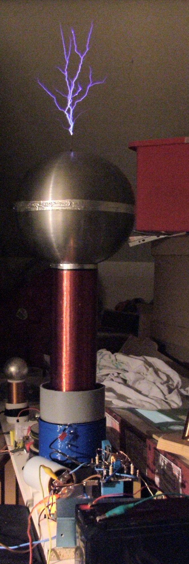
Experiments with a (DR)SSTC2 After all the fun I had with the small pretty SSTC I decided to make a more powerfull one. As I still had a few of the IRFP460's I made the SSTC2 Primary: 30T 2mm copper on a 4" PVC former.
(runs at 20T) & 1.5nF MMC The whole lot was designed using my SSTC calculator, this ment that I couls change values easily and see what the effect would be on the coil. Afer I got the bugs out of it it did work very well. |
 |
The Driver, built into a small alu case to prevent interferance from the working coil. The Secondary base current transformer is on the LHS, and there is two variables for the pulse width and the repitition rate on the RHS. I drive the GDT from a full bridge of IXY GDT drivers these are the two un-heatsinked TO220 case's on the LHS. |
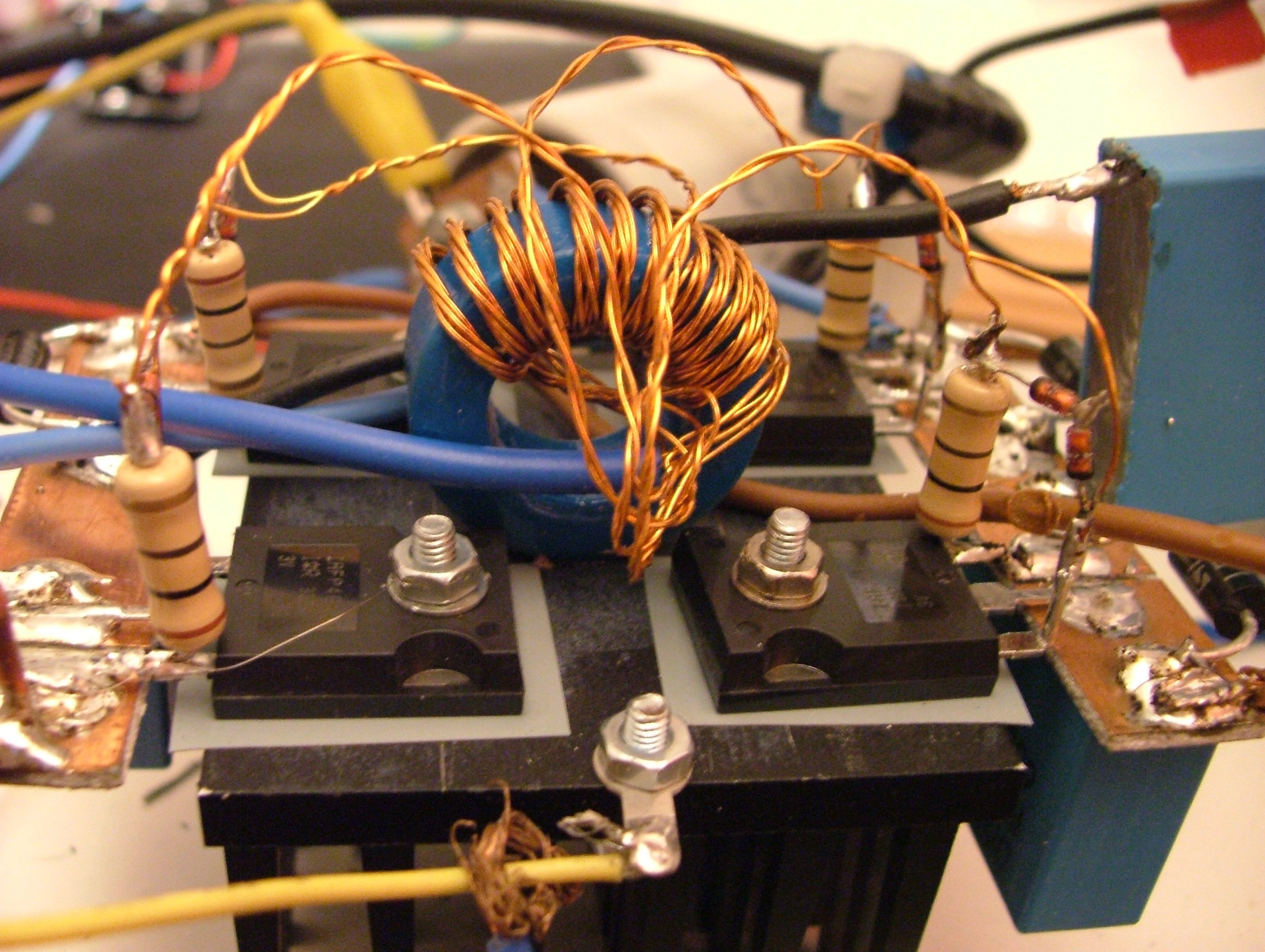 |
The Driver consists of 4 IRFP460's, each transistor has its own gate resistor and a pair of back to back 15V zenners to protect the gate from over voltage. This picture shows the construction of the GDT very well, 10T of 5 wires, each twisted together to prevent stray inductance, each winding is then split out, 1 to each mosfet and one from the driver.. The Bridge sits on an old pentium 3 heatsink, with no fan, It won't run CW, but with interruped drive, it hardly gets warm at all. Each IRFP40 is insulated from the heatsink by an insulating (but heat conducting) pad. |
|
The Results, After preliminary testing at 24V to ensure there were no drive problems and a few plays to get the secondary base current feedback working correctly I was ready for some power. Because I'm a coward, I started with a small 110V transformer charging
a 400uF @400V cap, |
|
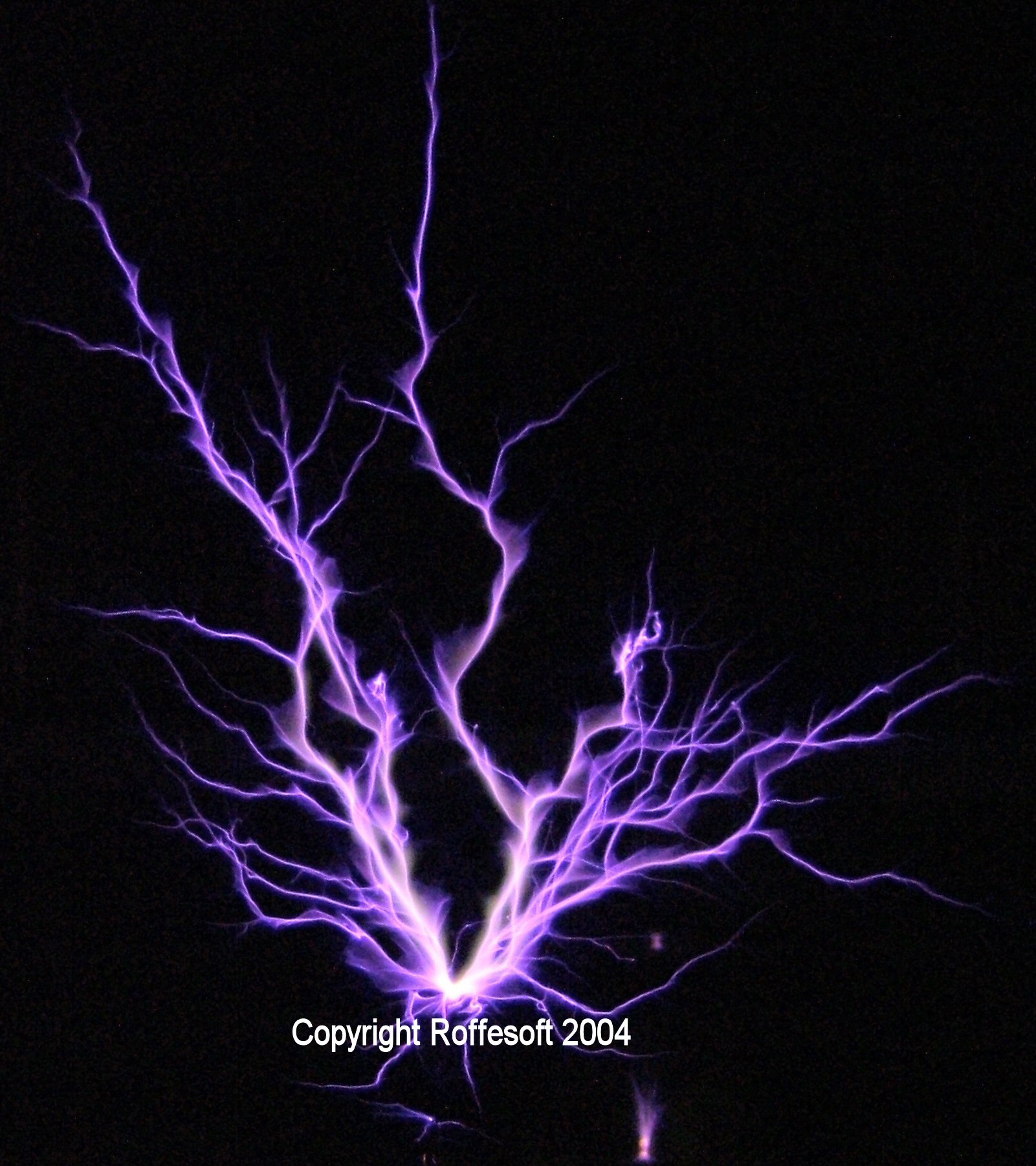
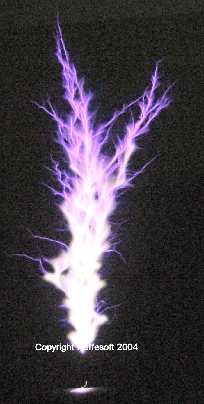
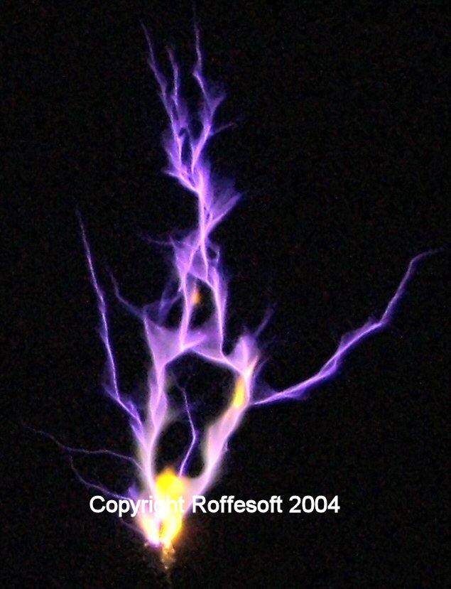
And of course
more power.... 11" sparks. & Hot 'n' jucy ones too.. |
 |
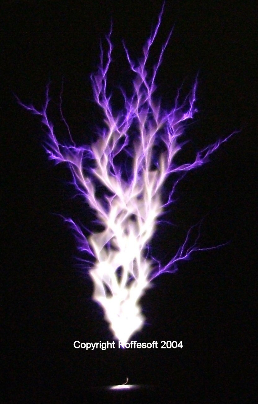
At full
power, I
stated to get some primary-secondary sparks, so I swapped my sphere topload
for a 8" diameter toroid made from 4" ducting, it cured the
problem. |
 |
After some
lower power experements with salt on a breakout, I tried with this coil,
Too much pulse width, and the arc was too strong to see the effect, but
with less power the effect of the salt is clearly seen,
|
 |
I tried the
coil with a primary capacitor making the SSTC into a simple DRSSTC (dual
resonant SSTC). One way to find out though.. |
|
Raising the
voltage over 200V blew half the bridge. |
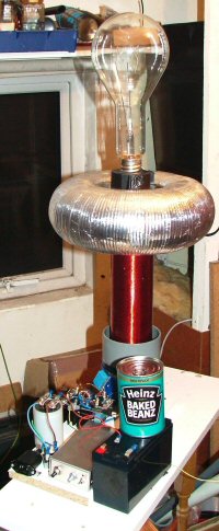 |
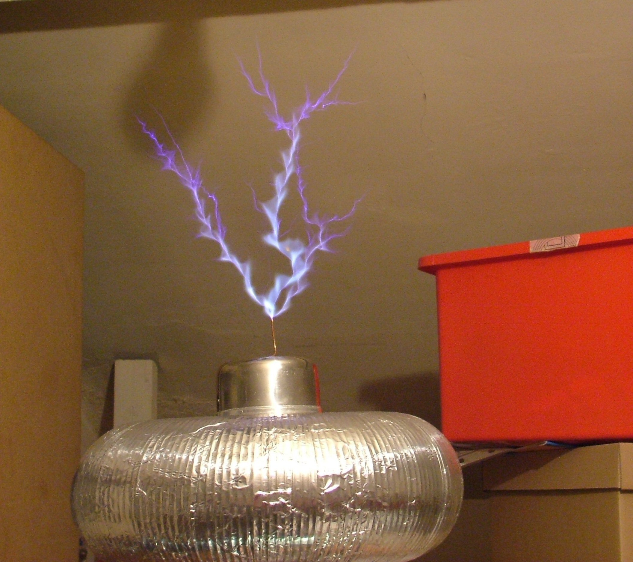
Experiments with a (DR)SSTC2 A Slight Diversion. So.... I added a 1000W 240v bulb to the toroid to give some Plasma globe effects. Pictures below.. |
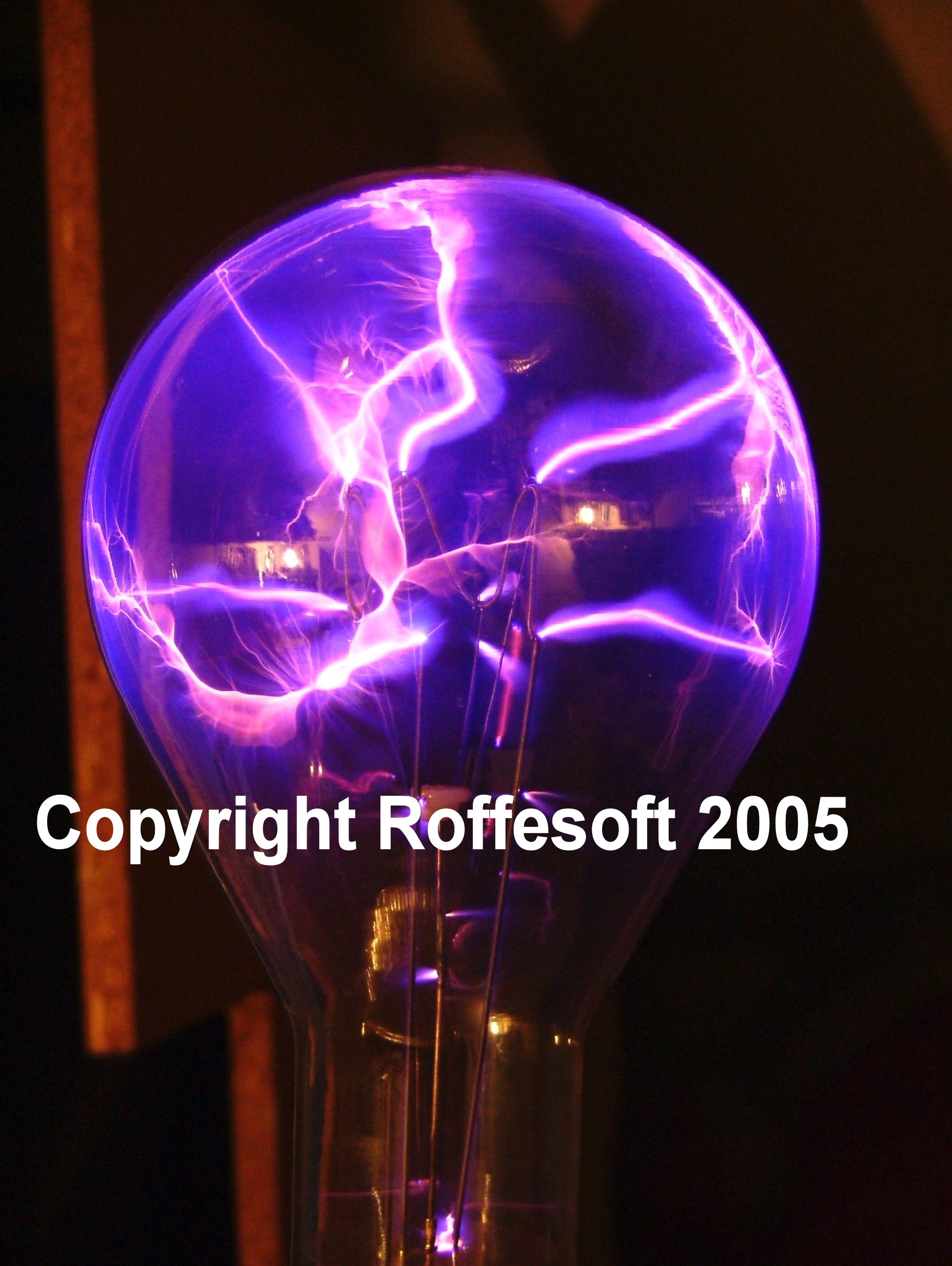 |
Running at low power Click Image for better picture |
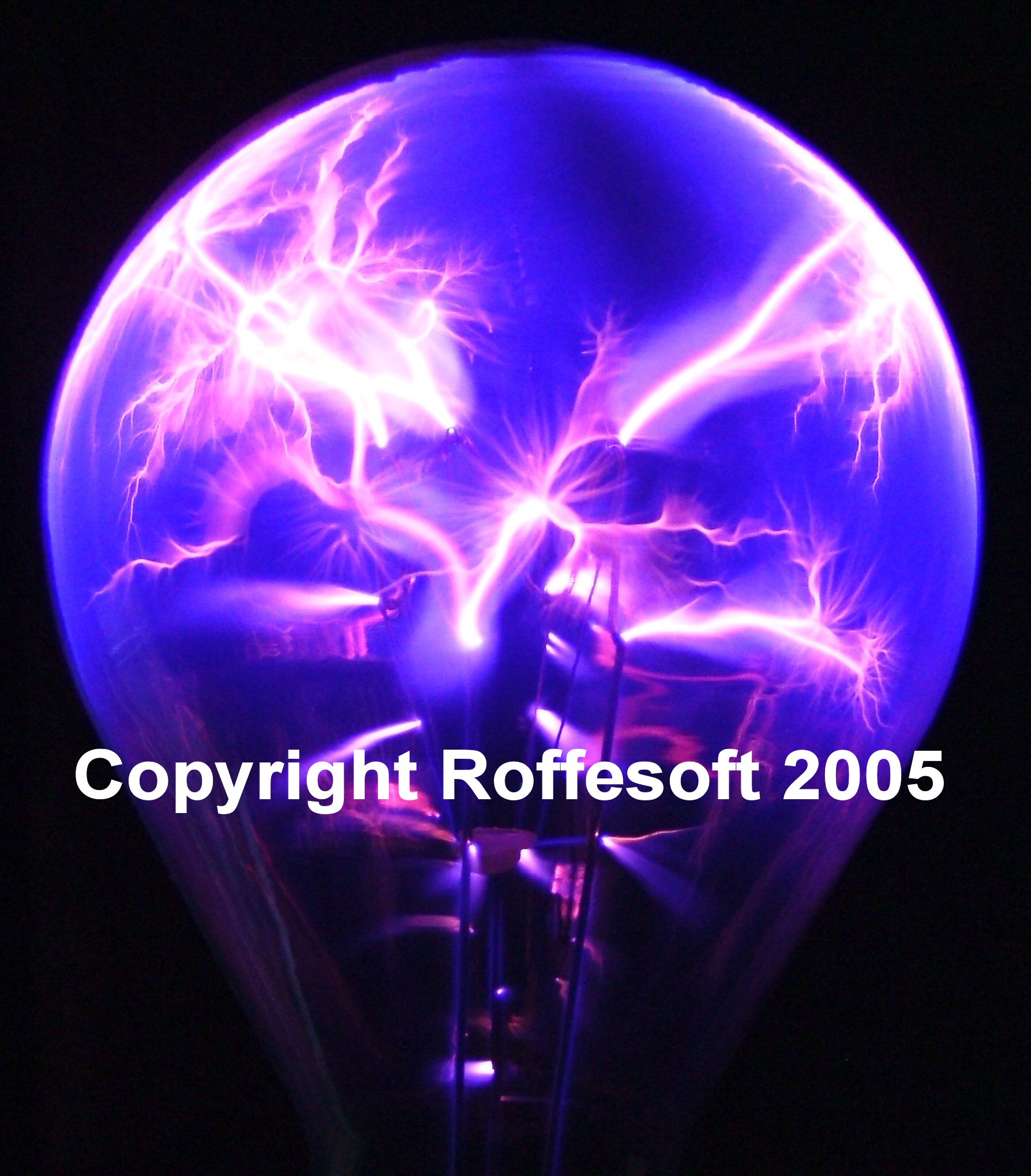 |
Running with more power Click Image for better picture |