• Category Archives High Voltage Experiments
  • Jacobs Ladder

    Equipment

    HV supply AC
    2 x coat hangers
    2 x Electrical terminals
    Insulating base board
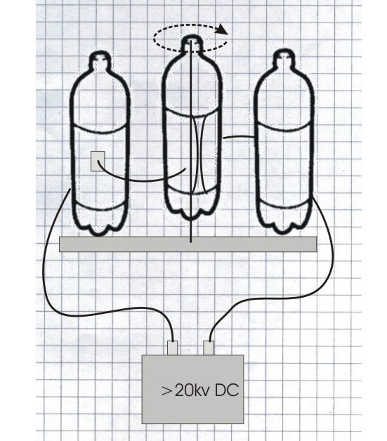
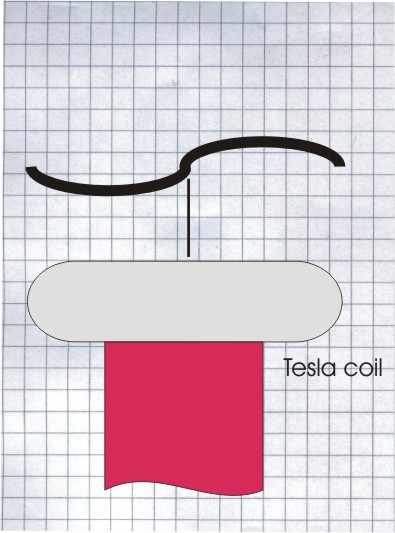
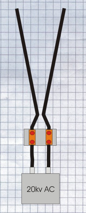
     

    Diagram

    jacobsladder

    Method

    Attach the two terminals on to a non conductive surface about 30mm apart

    Straighten the coat hangers in to two straight conductors. Bend the ends of the coat hangers slightly more than 90 degrees about 30mm from the ends and insert them into the two electrical terminals. Space the bottom of the wires 10mm apart and arrange the longer ends to spread out from the bottom to about 40mm wide at the top.

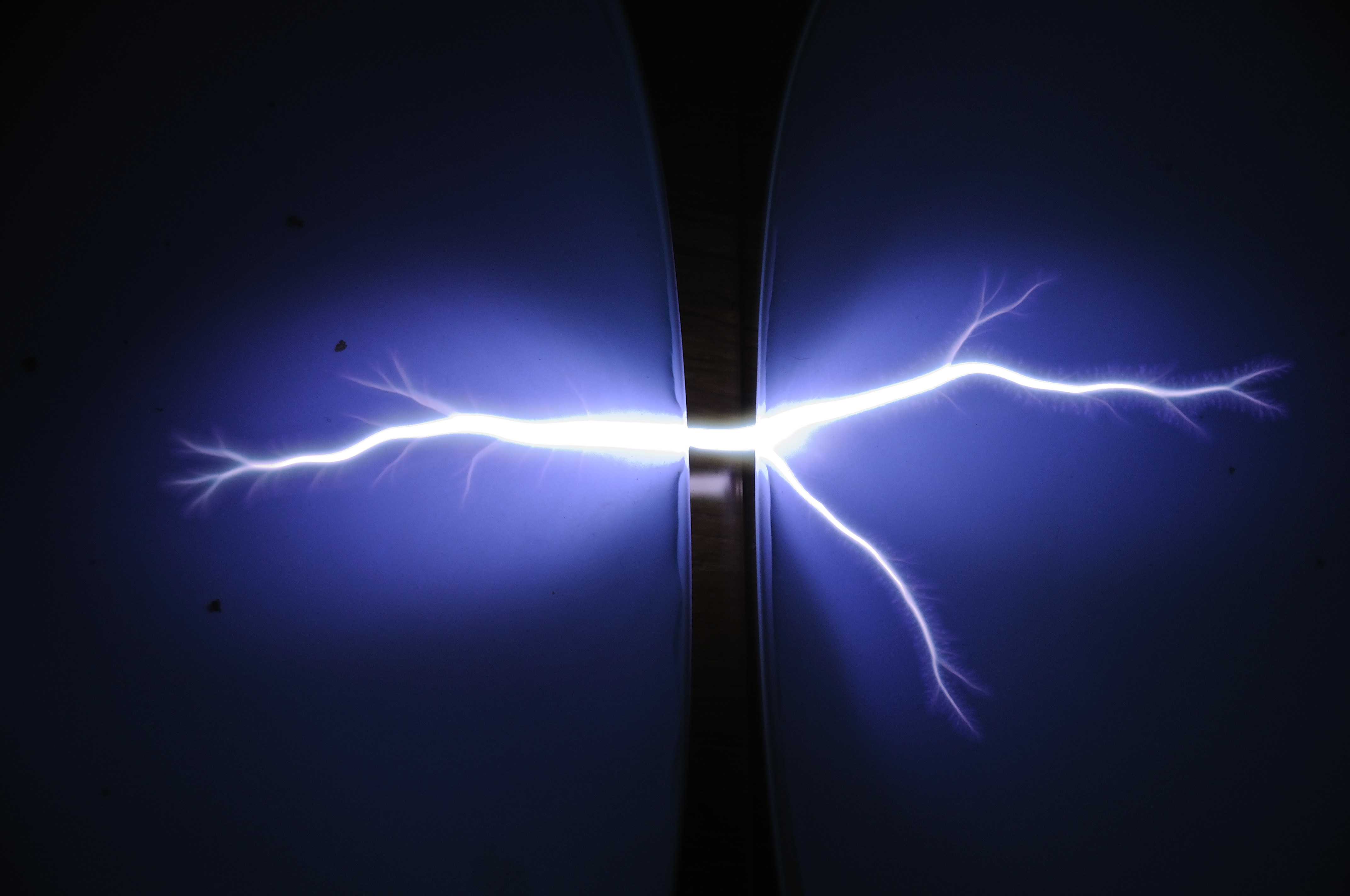
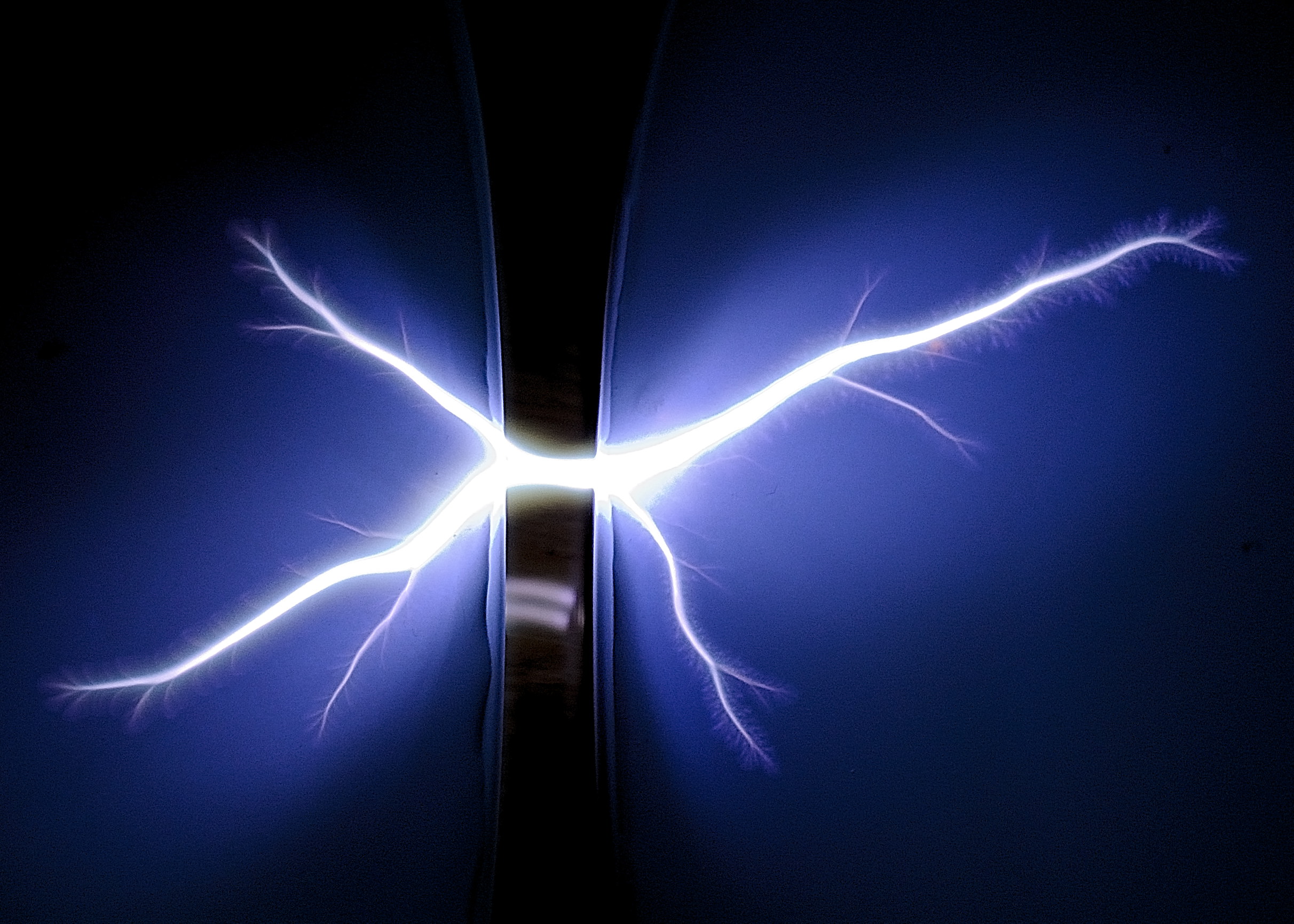
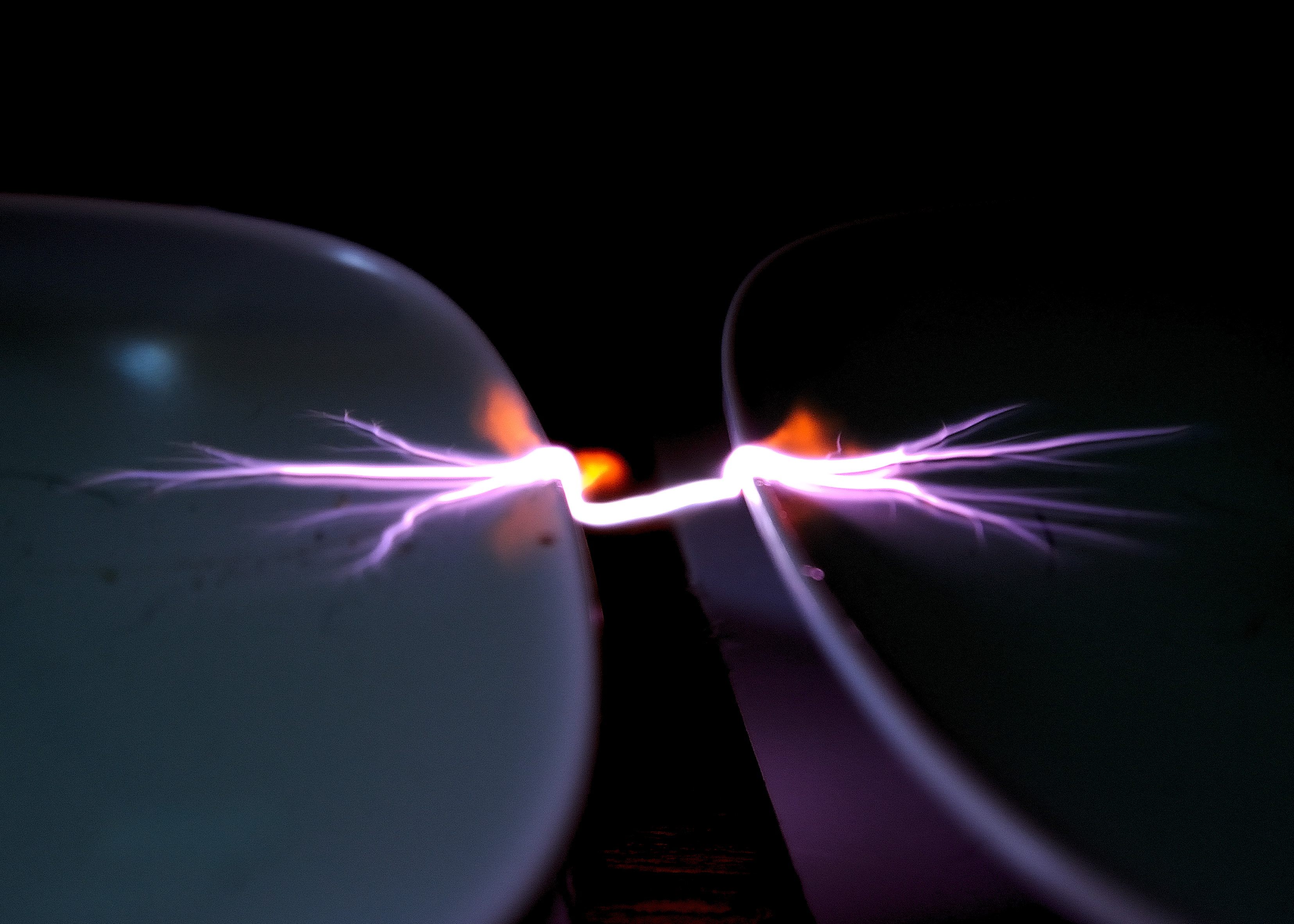
    Connect the HV supply and turn on. Arcs should start at the bottom of the V and work their way up. If the arc isn’t struck, turn off make the bottom of the V closer together and try again.


  • Franklyn Bells

    Equipment

    HV Generator 10Kv Plus
    2x Small Telephone Bells or similar
    Cotton or nylon string/twine
    Conductive ball (see https://www.extremeelectronics.co.uk/hvexperiments/conductive-balls-for-hv-experiments/)
    Small Bolts to mount bells
    Insulated wire
    Retort stand or support to attach twine to


    Diagram

    Franclin bells

    Method

    Mount the two bells onto the bolts through the hole in the centre of the bell. Mount the two bells on a non-conductive surface.

    Mount the ball on the string so the ball sits between the two bells.

    Adjust the two bells so the edges are 10mm away from the outside of the ball on each side.

    Apply high voltage across the two bells.

    Results

    A similar setup to above, but uses a short track of PVC pipe with the ball running on top rather than a pendulum. Supply is a TV flyback transformer giving around 25Kv.


  • Electrostatic Motor

    Equipment

    HV Generator 10Kv Plus
    3x Drinks Bottles
    Coat hanger
    Bluetack
    Adhesive backed foil
    Copper wire

    Diagram

    hvmotor

    Method

    Cut and unbend coat-hanger to give a single straight piece of wire slightly longer than the drinks bottle. File then end to a point.

    Clean out the bottles.

    On one of the bottles make a small hole in the middle of the base of the bottle so the coat-hanger can pass through cleanly. Make a slight indentation in the cap to this bottle to allow the sharpened end of the coat hanger to sit in the indentation.

    Cover the sides of the bottle with foil ensuring that there is a break in the foil on both sides. The foil should only cover the flat sides of the bottle, leave a 10mm gap between the end of the foil and the base of the bottle.

    Replace the bottle top and pass the wire through the base of the bottle to rest in the dent in the bottle top. Stick the wire down to a solid surface with the bluetack

    On the other two bottles coat the outside of the bottles completely with foil, again leave a 10mm gap between the bottom of the foil and the bottom of the bottle.

    Attach the wires to the two outer bottles pointing towards the inner bottle.

    Stand the two outer bottles near, but not touching centre bottle with the wires pointing to the sides of the inner bottle.

    Apply a high voltage to the outer two bottles.

    Refs:

    http://amasci.com/emotor/emotor.html


  • Ion Engine – Rotor

    Equipment

    HV Supply DC or AC
    Piece of stiff Card
    Aluminium foil
    Needle
    Cork

    Diagram

    rota-tesla

    Method

    Cover the card with the aluminium foil and cut out into a rotor shape. Find the center of the rotor and make an indentation in the car with the needle. Balance the rotor on a needle pushed into the cork. Attach one side of the HV supply to the needle and the other to earth.

    If a small DC power supply is used, a small rotor can be made 50mm or so in diameter.
    If a Tesla coil is used then you will need a larger rotor, Up to 300mm can be made with the method above. If you have a bigger tesla coil then make a larger rotor from copper tubing balanced on a needle point.

    Switching on the supply causes the rotor to spin. If the rotor doesn’t spin, move an earthed object nearer the rotor. For the rotor to spin, the bearing must allow the rotor to spin freely, Ensure the needle hasn’t gone too far through the card. The card should just rest on the end of the needle. If the needle has broken through the card the rotor will not spin freely enough.


  • Lichtenberg figures – Wood

    Equipment

    High voltage AC supply (NST)
    Two self tapping Screws
    Piece of wood (MDF is good)
    Cloth and a bowl of water


    Diagram

    lichtenburg-wood

    Method

    Screw in the two screws around 100mm apart. Using the water and cloth dampen the wood between the screws. Attach the HV power supply to the screws. Turn on the power a Lichtenberg figure will slowly be burnt into the wood. If the burning stops, remove the power and re-dampen the wood.

    Results


  • Lichtenberg figures – Water

    Equipment

    DC HV Generator
    0.05uF Cap @20KV
    Two Shallow Dishes
    Adhesive Aluminium Tape
    Insulated wires
    Water

    Diagram

    hvexperiments.

    Method

    Connect the HV supply to the capacitor. Attach a piece of foil to each of the plates so the foil extends down to the bottom of the dish on the top and attached to a wire on the outside.. Arrange the plates so there is a 10mm gap between them and the foil furthest away from the gap. Fill the plates until the water is level with the edge of the plates. Tilting the plates slightly may help to get the water evenly along the gap edge.

    Connect the two wires from each of the plates to each terminal of the capacitor.

    Charge up the capacitor until the gap between the plates breaks down giving a display across the surface of the water on both plates.

     Setup

    Img20130430_8689


    Results

    Img20130502_8983 Img20130430_8714 Img20130502_8949 Img20130430_8848

    Img20130430_8656