
 |
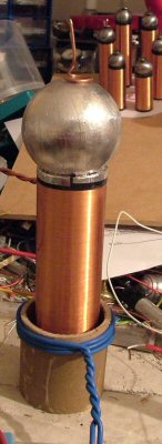
Experiments with an SSTC I decided to have a play with an SSTC, Having not prepaired anything or ordered anything, it had to be from parts I had lying around. So, Taking a pre wound secondary (1.3" diameter 800ish turns), a spare 2" topload ( wodden ball covered in alu foil) an old half bridge that I never used in anything (2x irp460 and GDT) ,my last IXY mosfet driver ic , a Transformer from an old VCR (with all of its outputs seriesed to give me 140V at about 300mA smoothed with a 400uf 400V cap.), primary of two turns of 4mm^2 around a 2" cardboard tube and I made a self resonant digital driver using the circuit from millie tess (bread boarded). Powered it up and "pif!" , sparks.. total build time 2 Hours... Mosfets get a little hot, I must add a heat sink.. |
 |
The first light was not too impressive. I had the interrupter at about 1khz and 50% mark space. |
 |
I played around with the coupling, and moved the primary coil to the top of the cardboard roll. givein an increase to the spark length (3"), and making them much more VTTC like.. |
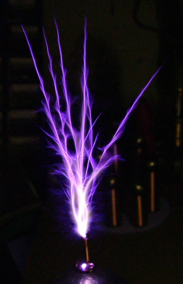 |
I had a thought, and shortened the breakout point to about 1/2", this really give me VTTC like sparks.. now 3.5" long. Next A full bridge and/or 240V... Need a heat sink... |
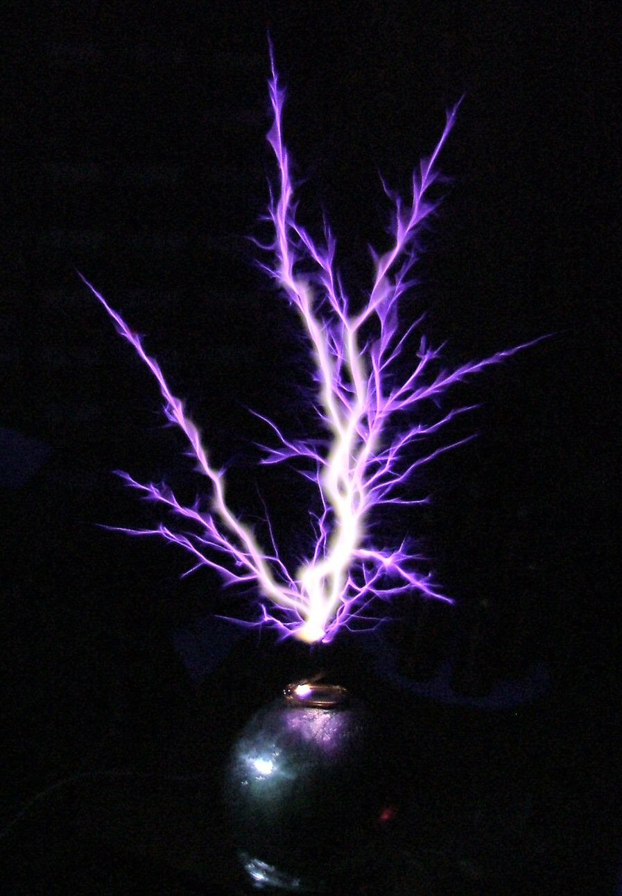 |
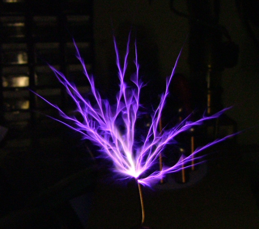
My order came for the IXY Drivers, so I now have a full bridge driving the GDT, giving me 10-12V of drive to the mosfets. 6" Sparks !! (the coil is only 5" tall). I need a
strike rail before I get any bigger ones!!!
|
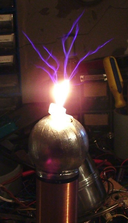 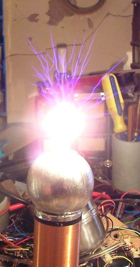 |
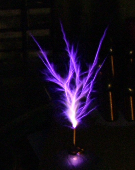
A quick play
replacing the breakout with a candle.
|
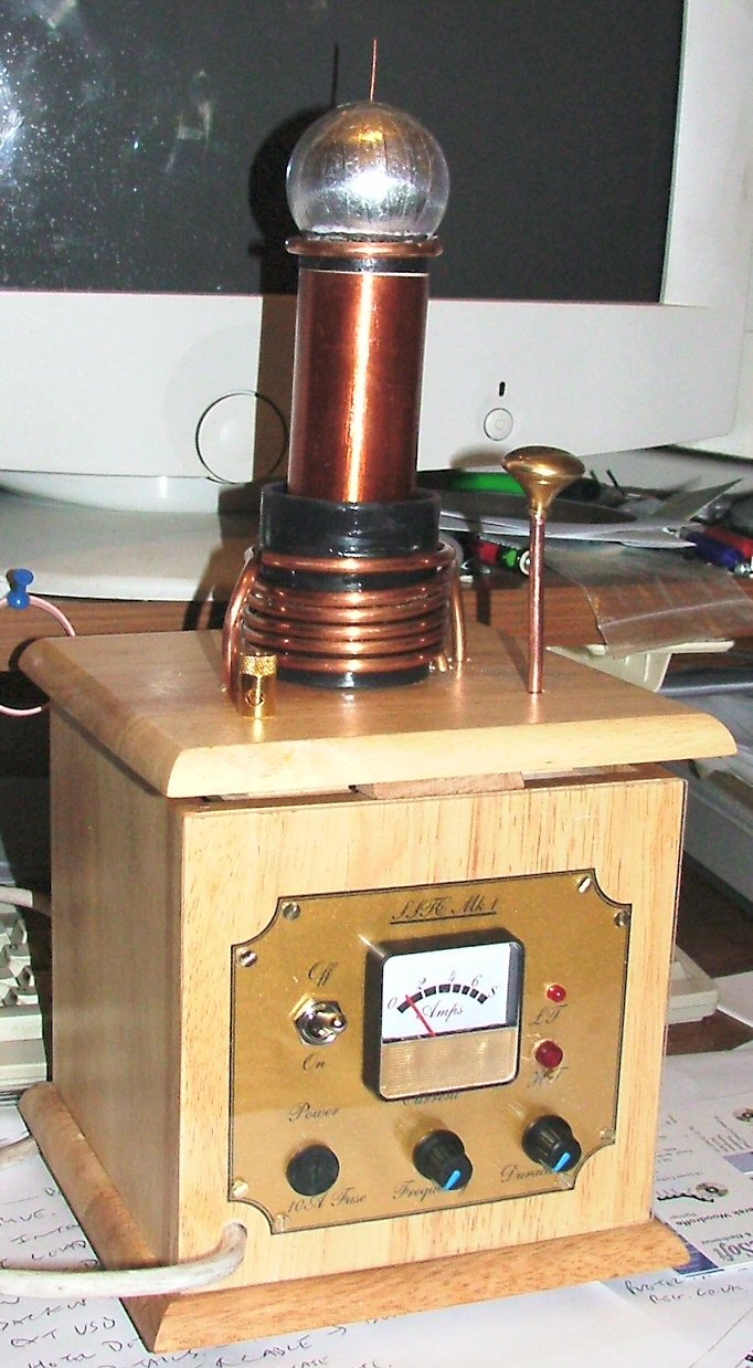 |
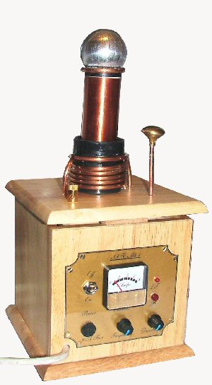
Boxing an SSTC So After the success of playing
with the SSTC, I decided to make a nice job of boxing it.. The gap around the rim is intentional to let a flow of air through the box. If I find a suitable set of brass fretwork or similar, I will cover this gap. The
single knob on a stick, is the feedback for the self resonant
driver. |
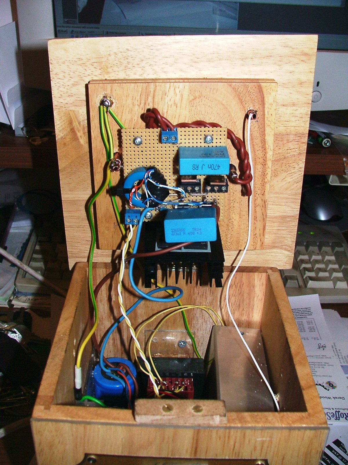 |
The Electronics is rather a tight fit into the box, All of the half bridge is fixed into the lid, (note heatsink) with the GDT. The HV stuff is on the LHS of the box and the driver is on the RHS. Running the coil, does not quite give the same size of sparks that it used to in the bread-boarded version. This is probably due to the extra turn on the primsry (for reliability) and the looser coupling due to the primary beign spread over 40mm rather than 10mm. |
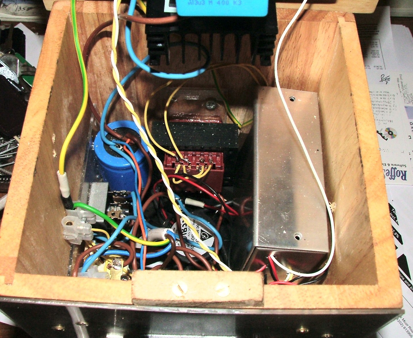 |
A better view inside the base. Somewhere at the bottom is the fan.. I had
HUGE problems with the driver, this close to the primary coil the analogue
PWM circuit for the modulation was suffering from EMP, every time the
coil struck the pulse would turn off the PWM and the on-time would end short,
then on the next pulse it would let out one long burst and blow all
the sillicon. |
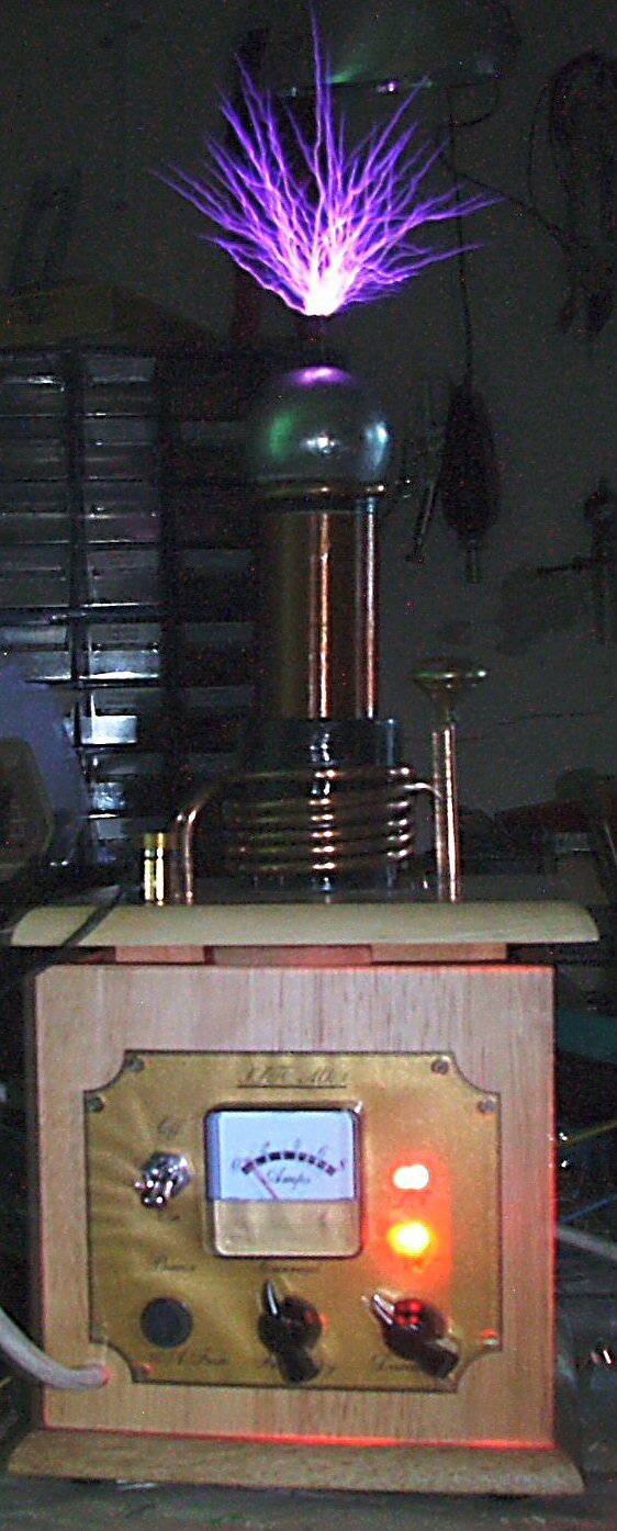 |
Running... |