Category Archives: Tesla Coils

Teslathon & tesla workshop/talk Venues needed

EE are actively looking for venues for teslathons in the East Midlands for next year.

Places to hold our events are getting few and far between, mostly because of our “special” requirements.

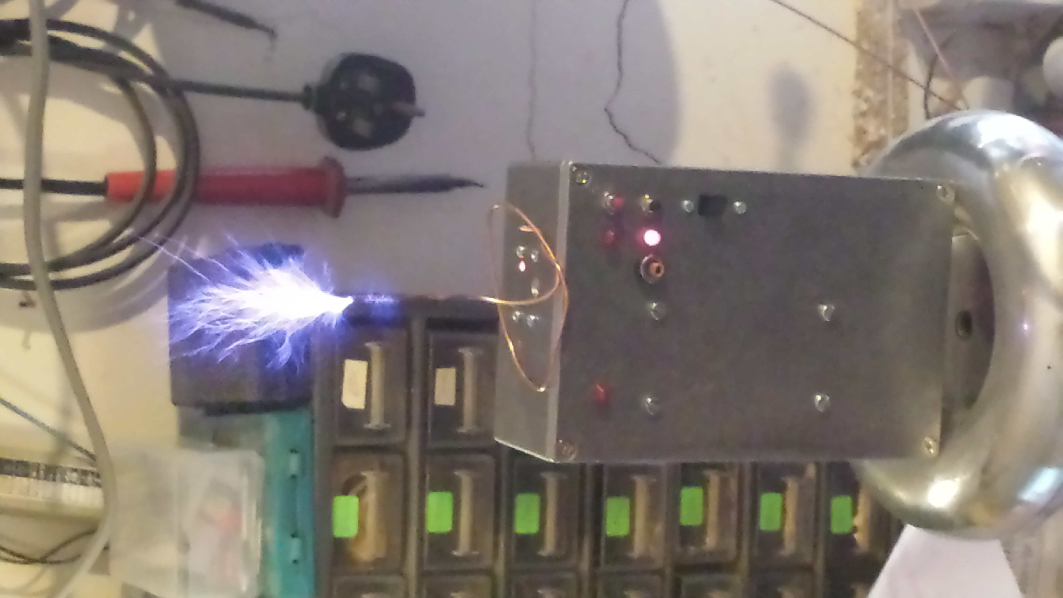
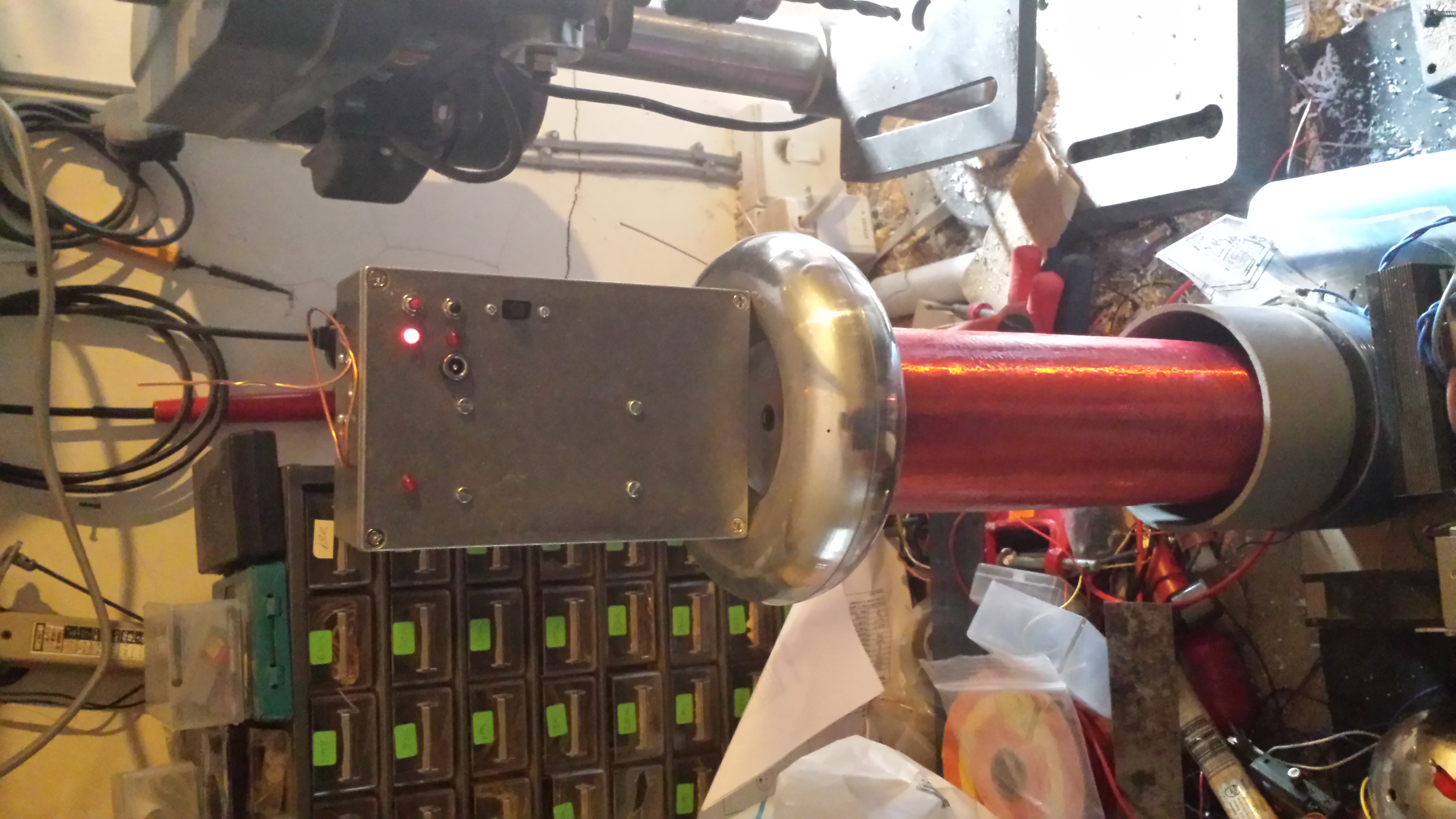
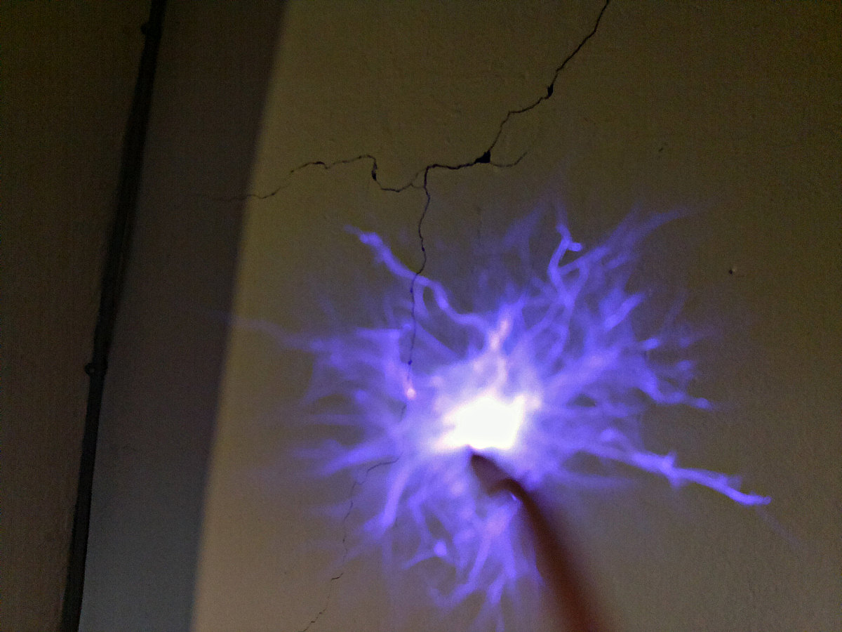
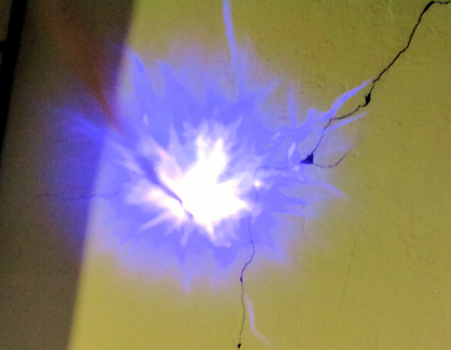
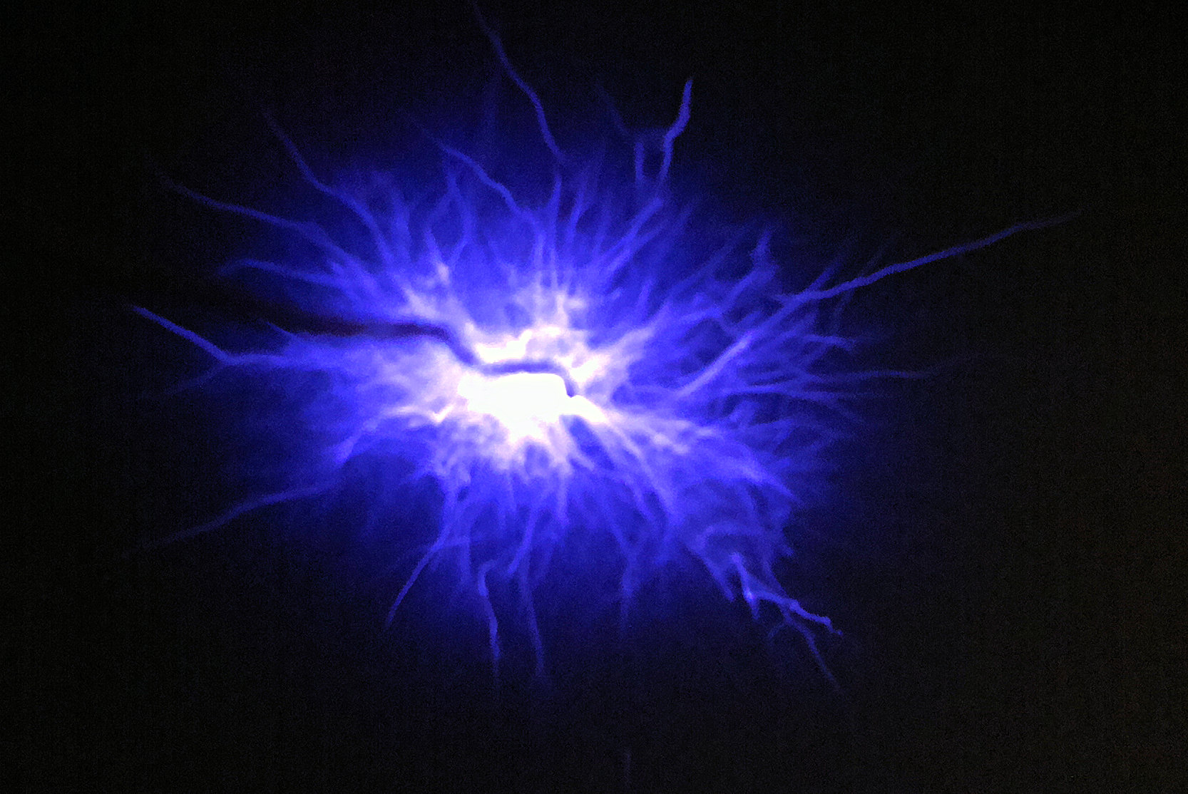
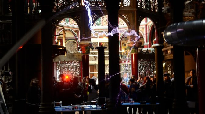
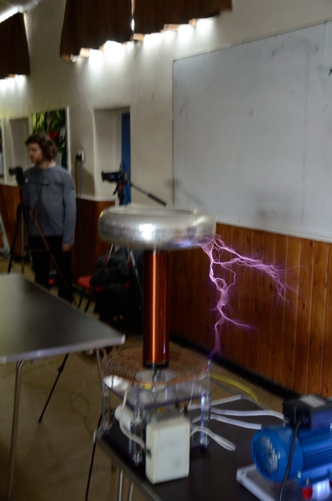
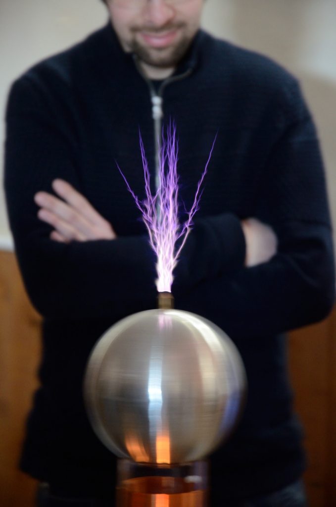
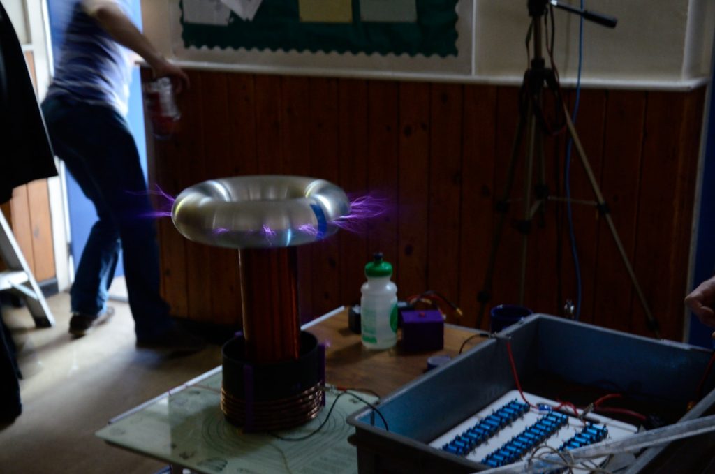
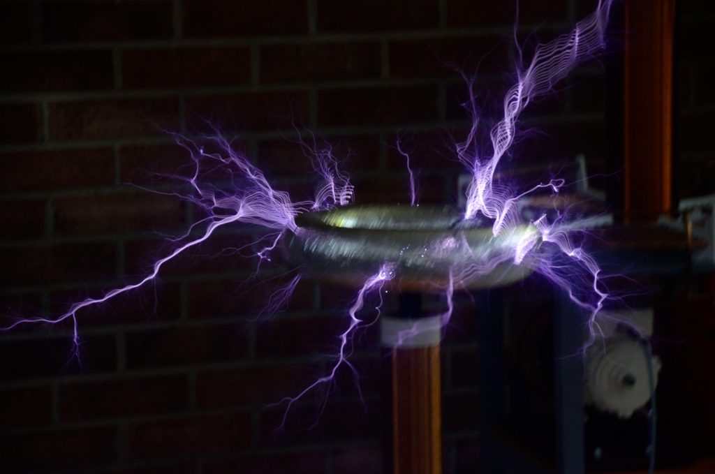
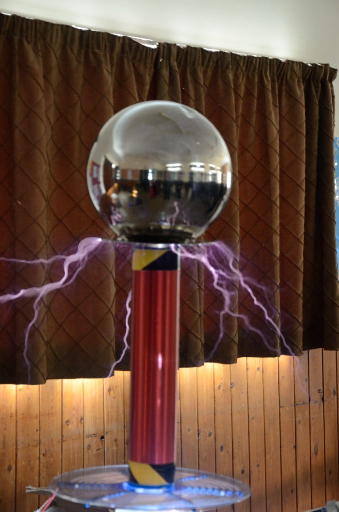
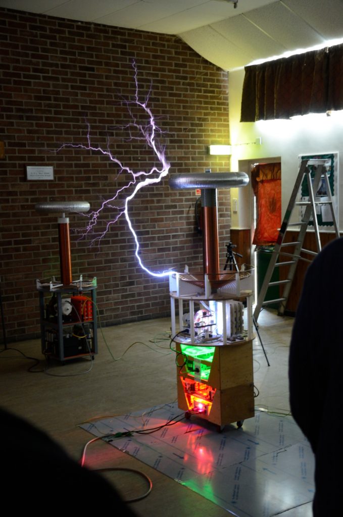
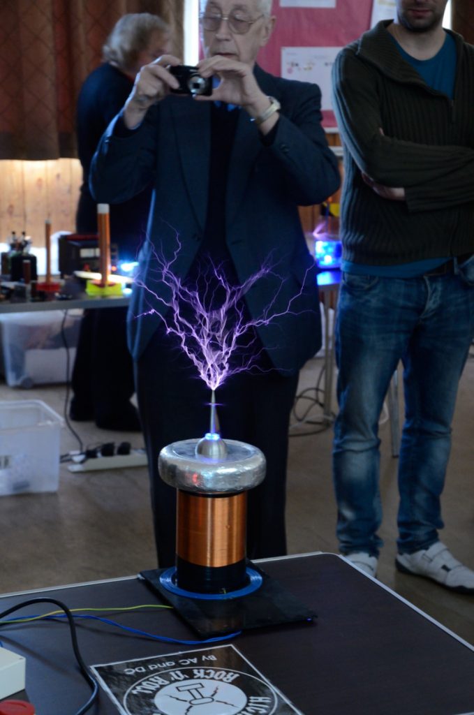
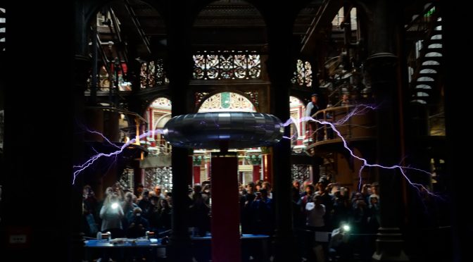
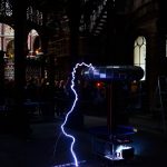
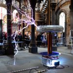
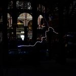
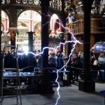
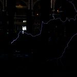
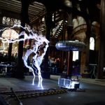
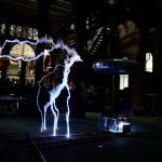
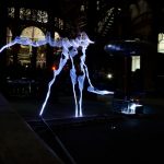
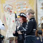
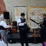
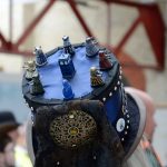
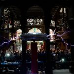
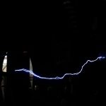
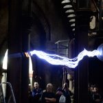
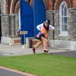
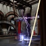
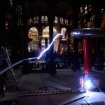
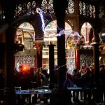
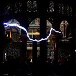
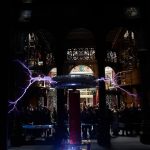
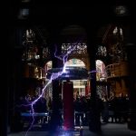
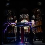
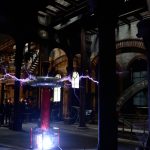
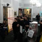
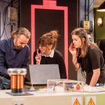
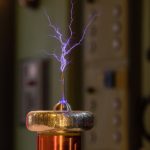
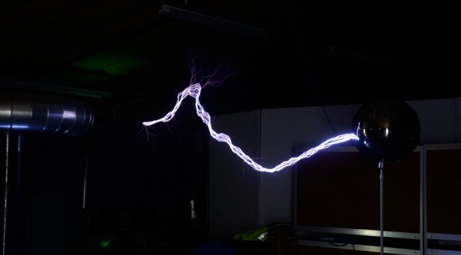
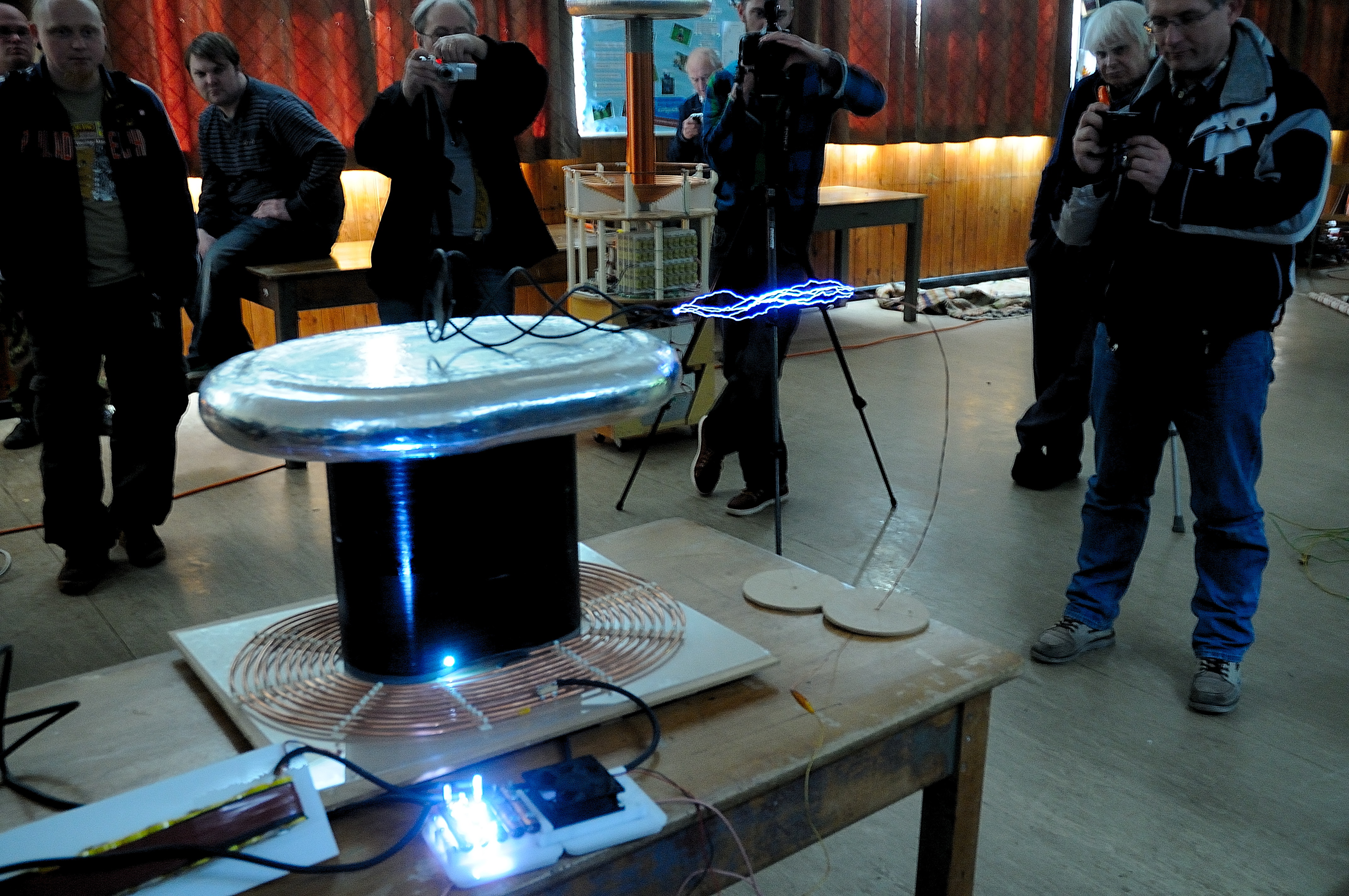
What is a teslathon : A tesalthon is a meeting of tesla coil enthusiasts. Our tesla coils vary in size from tabletop to 3M tall and are all built by amateurs.

I have been running teslathons for 18+ years and have Risk assessments and method statements to cover the H&S aspects to our hobby.

So what do we need?

The Must have’s

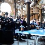
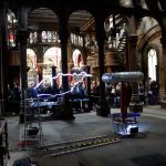
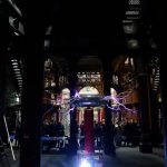
A room with tables a minimum of 11M x 8M in size, on the ground floor that can be blacked out and a ceiling height of ideally more than 4M. Bigger of course is better. We usually have 20 or so coilers and 30-60 visitors to the events.

Plenty of 13A sockets (for our bigger events, a 32A Commando or accessible cooker socket would be needed, or an electrician on site to give support.)
Some method of providing a separate electrical earth. 10 or more tables.

Tea and coffee making facilities 🙂

Other needs (can generally be worked around)

The room needs a minimum (ideally non) of Burglar alarm, Fire alarm or network cables. Electronic lighting can be OK, but they must be high the ceiling. Fire sensors are generally OK, but they must not be of the ionisation type.

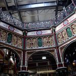
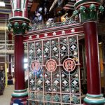
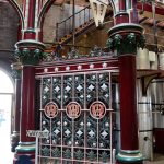
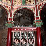
Ideal Venues are usually industrial museums or metal skinned warehouses/barns as these have a minimum of electronic equipment. We would like to work with the venues own insurance if possible, but we can provide our own if needed.

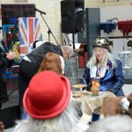
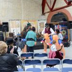
I also arrange workshops and talks with lesser requirements, so most venues can be used for something.

We can work in two ways, either a daily rental for the hall, paid by us,or we can work as a ticketed event to raise funds or awareness for a museum, venue or charity.

Before any booking, I would need to assess the venue for safety and suitability.

Have a suitable venue? (Or would like a talk at your venue) contact me tesa@extremeeectronics.co.uk

Details of past events are here https://www.extremeelectronics.co.uk/cambridge-teslathon/ and here https://www.extremeelectronics.co.uk/nottingham-gaussfest/

PIZero Tesla Coils at the RI Christmas Lectures

Earlier this month it was my great honor to be invited to demonstrate the PI zero tesla coils at the Royal institution Christmas lectures.

The Christmas lectures were a Christmas institution when I was growing up and they formed a great part of my education, especially the ones by Eric Lathwaite. This year is their 80th televised Christmas Lecture, I’m sure in that time it has inspired the lives of many many children to investigate science, and long may it continue to do so.

Behinds the scenes at the lectures was incredible, the organised chaos that was happening was untrue. There were 20+ experiments in the lecture (the first of three) and moving them in and out of the theater was a very well choreographed scientific dance.

I have every admiration to the RI and Windfall Films that produce it.

Walking in to the theater and standing where Faraday and not to forget, Tesla himself had lectured, I can’t explain the feeling. Oh, and the 350+ kids watching you… No Pressure…

The theater is incredible, it’s so much smaller than it looks on TV, add three cameras, a lecturer and 10+ support staff (dressed in black), it doesn’t leave much room for demonstrations that need a couple of meters exclusion zone for safety.

What will be featured on the lecture on Boxing day, not a clue, as is usual with any filming, its down to the final edit.

Even if I don’t make it on to the show, watch anyway well worth it for kids of all ages.

Behind the Ri Christmas Lectures- Show 01, 2016 Mark Parker – Standup Maths (warm up guy)

This Lecture is the first to go out BBC4 20:00 Boxing day 2016

The video is now available at http://richannel.org/christmas-lectures/2016/supercharged-fuelling-the-future


Details of the PiZero Tesla coils 

Electronic Tesla Coil Power

Tesla coils, either classic (with spark gaps) or electronic (with transistors) are impulsive devices. Measuring and comparing power is much more complicated than it initially appears.

With a small electronic coil, the peak current to the primary of the tesla coil can be up to 1MW. This sounds huge, especially for a device that is sitting on your table top and is not engulfed in flames.

But, the answer is simple, the 1MW is only drawn for a very short time and each pulse grows exponentially to this maximum, it isnt constant. In the terms of a small table top electronic coil, the power pulse can last for 100-150uS (1/10000th of a second) and is repeated maybe 500 times per second, during each pulse the current grows exponentially so this gives an average power of roughly 4KW (1Khz – 100uS)

20160111_202808

I couldn’t run the coil like this for long without overheating so I allow this for very short periods of time, or if the on time is known to be longer I will limit the output of the coil to that which is sustainable.

As you can see from this, doubling the frequency doubles the power. This explains why the lower frequencies have smaller sparks.

It also explains why I like ‘plonky’ percussive electronic music playing on my tesla coils.


Save

Save

Save

New Tesla Coil Phenomenon

After measuring the weight of my new PiZero Tesla coil project setup, I forgot that one of the tesla coils was still on the scales and applied power. I was very surprised to find that the weight of the running coil varied as the power was applied.

I of course instantly thought there was some electromagnetic effect, so I swapped the expensive scales for a cheap plastic (and staggeringly inaccurate) set. These have no metal parts inside apart from a single spring, so cannot be affected by electromagnetic fields. But they clearly showed the same effect (within an order of magnitude) as the other scale. The table the tesla coil was on was wooden and there was no other electrical equipment near by that could influence the scales.

I made a quick video showing the anti-gravity? effect. Please note that the cheap scales have a huge turn back error, and don’t always return to the correct weight, in fact I think they are pretty much useless even for cooking, never mind a scientific experiment.

After making the video I had more time and so did a much better analysis of the effect.

I checked that the wires were not contributing to the effect, if anything they were producing an additional weight due to their natural springiness, but they didnt move either on their own when put near a powerful magnet. I also checked for any static magnetic fields with an orienteering compass and found nothing over and above the earths natural magnetic field.

Futher testing

After further testing it appears that for every 1.5w RMS of energy put into the tesla coil the tesla coil becomes lighter by roughly 1g. Sometimes the effect isn’t immediate (as the video shows) and can take a second or two to appear or disappear. This hints at the building up of a field? around the device.

tcwl

Another possible source of the weight change could have been the ion drive (ion wind) effect, well known to any high voltage enthusiast. I have discounted this for two reasons. 1. The effect looses weight in my setup. 2. The scale of the weight change is far in excess of the force of the ion wind from similar powered tesla coils.

I have tried experiments with a simple low power Royer and Slayer circuits and I have not seen the effect. I suspect that the effect only appears at higher powers. (100W+ ?)


Help with research

I would like for  this observation to be verified by other tesla coilers. If possible please set up a test with you own coil. Please give an idea of the type of coil, the power in, the initial weight of the coil, any weight change (+ or-ve), details of the weighing system used and any notes regarding the effect. I will list the results and coilers details on this page as a central reference for other experimenters. Please note the safety warning below when making measurements.


Further study.

Effect with CW and valve coils.
Effect with static gap and rotary coils. (magnifiers?)
Accurate weighing of running high power Fly-back circuits and car ignition coils.
Industrial Inductive heating – reported effects of the molten metal suspended in the working coil, a connected phenomenon ?


Other Thoughts.

Did Tesla know of this effect ?
Probably not, His coils although powerful were very heavy and securely bolted to the floor, it is unlikely he would have noticed the small change in the weight of his devices.

Electric space propulsion – microwave thrusters or quantum vacuum plasma thrusters (QVPT)
http://ntrs.nasa.gov/search.jsp?R=20140006052
There is a lot of similarity with these devices, they  both use high voltage and work with large RF fields, maybe there is a connection?


Warning / Safety

As modern tesla coils become smaller, lighter and more powerful, the above effect could have more and more significant effects on these tesla coils.  I would strongly suggest that when running any tesla coil they are securely fastened to the ground with a safety chain and the possibility of loose/floating tesla coils should be included in any risk assessment until we know more about this phenomena.

Any questions regarding this effect, or to give your own results for inclusion on this page, please contact tesla@extremeelectronics.co.uk


UPDATE 1/4/16

As of midday today all of the observed behaviour has stopped and I cannot repeat the findings. I can only assume this was a glitch in the space time continuum that lasted for 12 hours.


The 1MV Tesla coil myth – Spark growth

It is often said to me that a Tesla Coil produces 1,000,000 V or more.

This is a common misconception. Unless you have an absolutely huge Tesla coil, the actual voltage at the top load is much smaller.

The mistake comes from the widely accepted rule of thumb that the voltage that an electrical discharge will jump determines the voltage present, in normal air at atmospheric pressure this equates to 30Kv per cm .  [Paschen’s Law] So it is easy to see that if a tesla coil produces sparks that will jump 30 cm or so, this means that the voltage on the top load must be roughly 1MV.

Unfortunately the situation on a tesla coils top load is a bit more complicated and the 30KV/cm rule does not apply in quite the same way.

The physics of the arc itself needs to be taken into account and the Radio frequency AC that is created. The Tesla coil is effectively a high voltage, high impedance AC current source [Tesla Coil – Output voltage] . So when the spark is being created as the spark grows it forms a  capacitor that draws current from the tesla coil reducing the top load voltage.  This effect happens as soon as the torroid breakdown voltage has occurred and gets progressively worse as the spark leader forms. This is therefore governed by the voltage breakdown of the minor diameter of the tesla coils top load

The maximal achievable potential is approximately equal to the sphere radius R multiplied by the electric field Emax at which corona discharges begin to form within the surrounding gas. For air at STP the breakdown field is about 30 kV/cm –  [https://en.wikipedia.org/wiki/Van_de_Graaff_generator]

So the voltage on the top load of a tesla coil tends to be slightly more than the standoff voltage of it smallest diameter.  Vmax = R·Emax (R = Radius, Emax = Breakdown voltage in air 30Kv). For a teslacoil with a 20cm (minor) diameter top load this is around (20cm/2) * 30Kv = 300Kv

The minor diameter is d

But… 300Kv will only give sparks of 10cm according to the 30Kv/cm rule, Tesla coils can easily achieve better than that?

This is where the second aspect of the tesla coils output comes in to play. The voltage on the top load is both AC and Pulsed. Each burst or pulse of Radio Frequency (RF) creates a 10cm long (using the example above) arc leader from the available 300Kv. This heats and ionizes the air, making it conductive this is what you see as the arc in the air.

If very rapidly after the first burst of RF comes another,  the channel won’t have had time to dissipate so there is a conductive channel the new pulse can use. The energy rushes to the end of this ionized channel and tries to create another 10cm leader there. Not only does this almost double the spark length, but the energy also re-ionizes  the channel. This continues with the third, fourth, n … pulses, each time adding on a slightly diminishing (due to losses) leader to the existing spark.

This continues until something disrupts the channel usually the air rising as it get hot.

This can be easily proved with a modern electronic tesla coil. Set the coil to produce a single burst of RF, this gives a discharge that can be measured using the 30Kv/cm rule and can give a fairly accurate indication of the terminal voltage.

So unless you see a tesla coil with a 66cm minor diameter top load it isn’t producing 1MV

The BIGG coil of Oklahoma, probably the only true 1MV tesla coil.

Save

Stand on Teslacoil

Img20130914_10305

[shortlink url=”http://tinyurl.com/msd4o8v” title=”Continued From V8 Tesla Engine”]

After playing with the V8 Tesla engine I realised that I could build a stand on tesla coil. The lack of mains power could make this “fairly” safe.

So I started with a topload that was big enough and strong enough to stand on. I started with a pair of 110mm PVC tubes and joined them together. The thought was to make an oval tesla coil (big mistake).

After winding the secondary, by hand (1000T of 0.33mm wire ) on to the former I started to realise that there was a problem, the wire stretched slightly and started to sag between the two tubes. To give the wire some support I wound PVC tape around the coils as I completed them. This was partially successful, but as I had nothing to loose so I continued.

IMAG0317

The Topload needed to be strong enough to

stand on too and smooth and an oval.

So I started with an MDF former of 3 oval sheets spaced to a total height of 2.5″, and an external wrap of pipe lagging to give the external shape.

Over this I added paper mache and then a covering of plaster and PVA glue to give it strength. This last layer could be sanded to smooth out the edges.

Img20130914_10302The Primary, I quickly roughed out from 50′ of 5mm break pipe held in an oval spiral with cable ties and adhesive.

The output from the V8 tesla engine is fed into a primary cap and an crude sparkgap.


Img20140301_11421

Here is the coil working at the Nottingham Gaussfest.

Note that the problems with the secondary coil are starting to show with a breakout at the bottom.

But it was worth having a go at standing out the coil. After a while I found that the tuning point changed only a single turn when I was standing on the coil.

Below is a video of the first run with me on top.

So I realised that the secondary needed to be re-built The pictures below show the damage.20140305_194312

20140305_194331
20140305_194348


So the rebuild begins

Img_20140406_1123

This time I’ve packed out the space with some cardboard in the void between the PVC pipes and sheets under the coil bridging the two pipes. The cardboard is held in place with many layers of adhesive craft paper that was varnished before the wire was wound on.

The finished article looks a load better then the old one, but there is still some minor ‘droopage’ between turns. So the coil was heavily varnished after winding.

Hopefully it will not suffer the same breakouts as the old.


Also I decided to clean and re-mount the sparkgap the old copper pipe gaps were a little? corroded.

The Sparkgap is mounted on to a channelled acrlyic chamber that allows a high volume fan to blow air over the gaps for cooling and more importantly spark quenching.

20140208_163246 20140215_154730


Better results from the new coil

Tesla Coil Tuner

First light of a Tesla Coil tuner.

Old TC Tuner
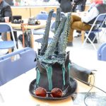
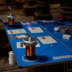
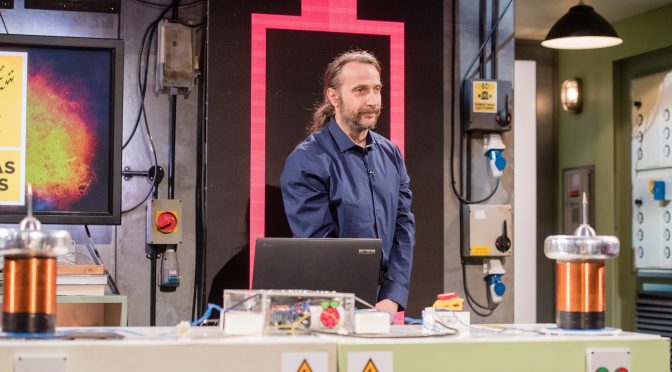
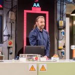
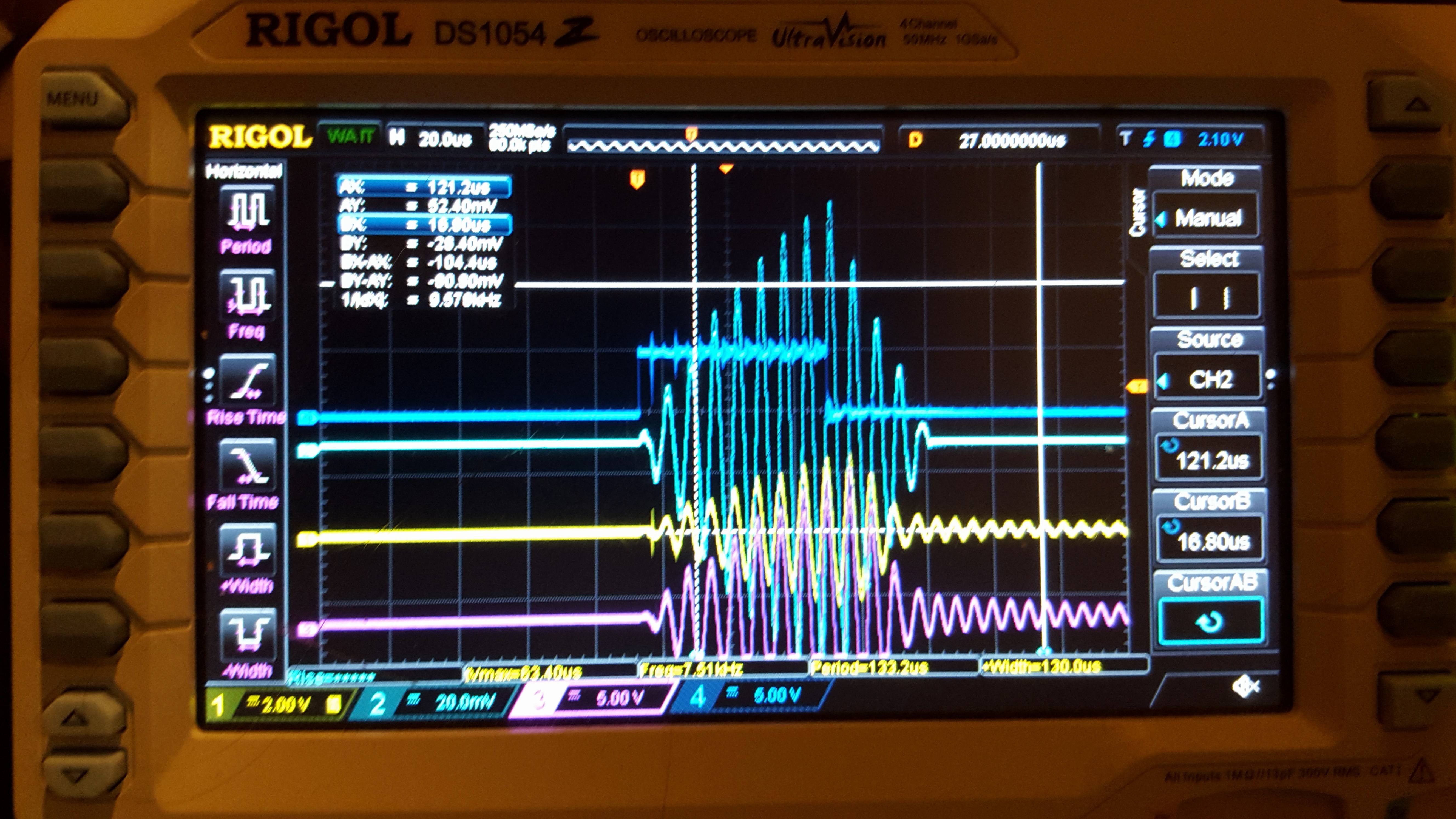
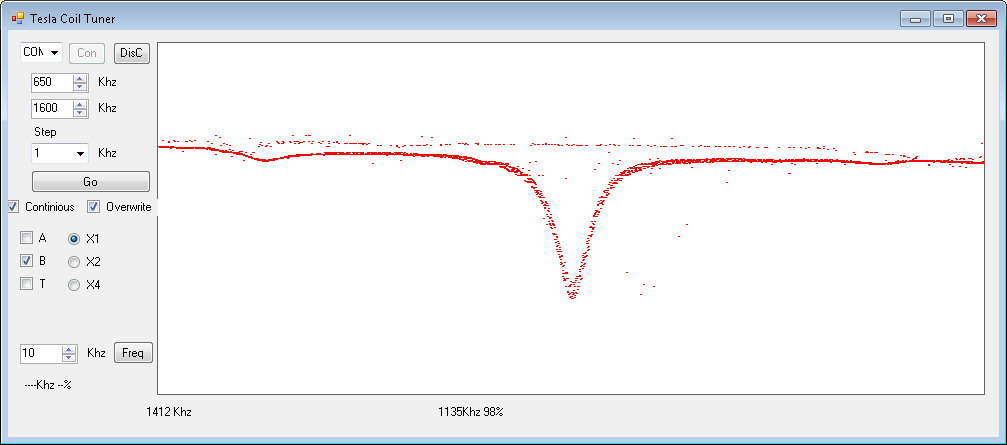
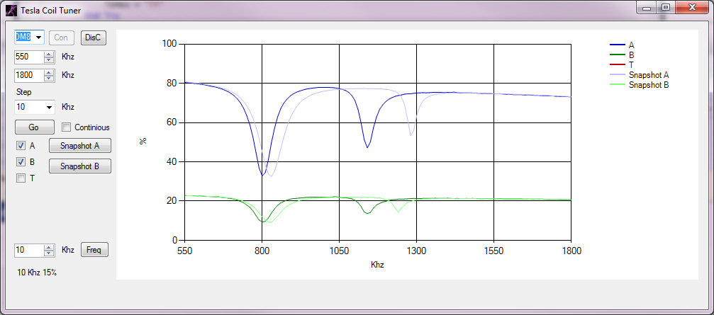
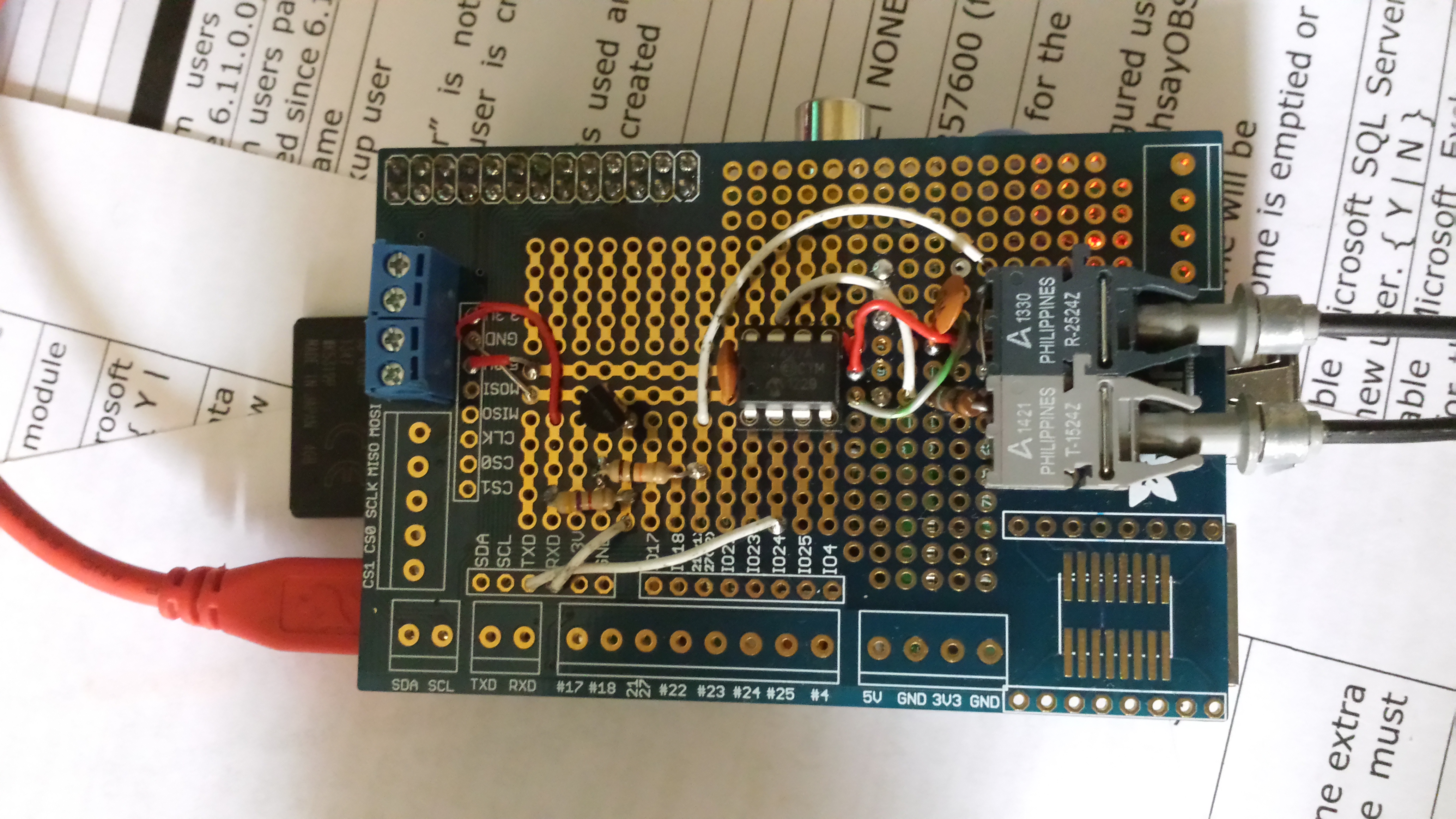
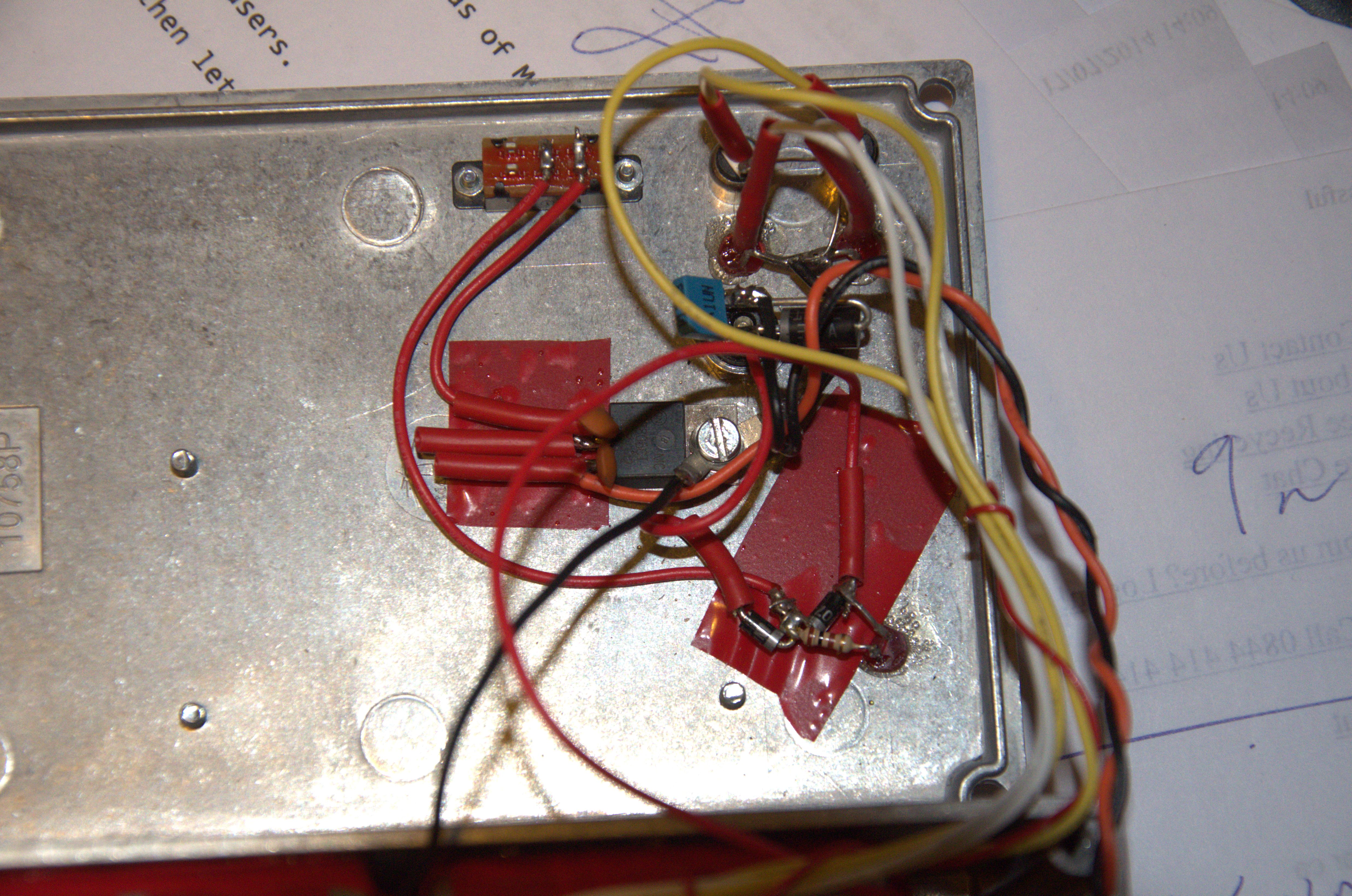
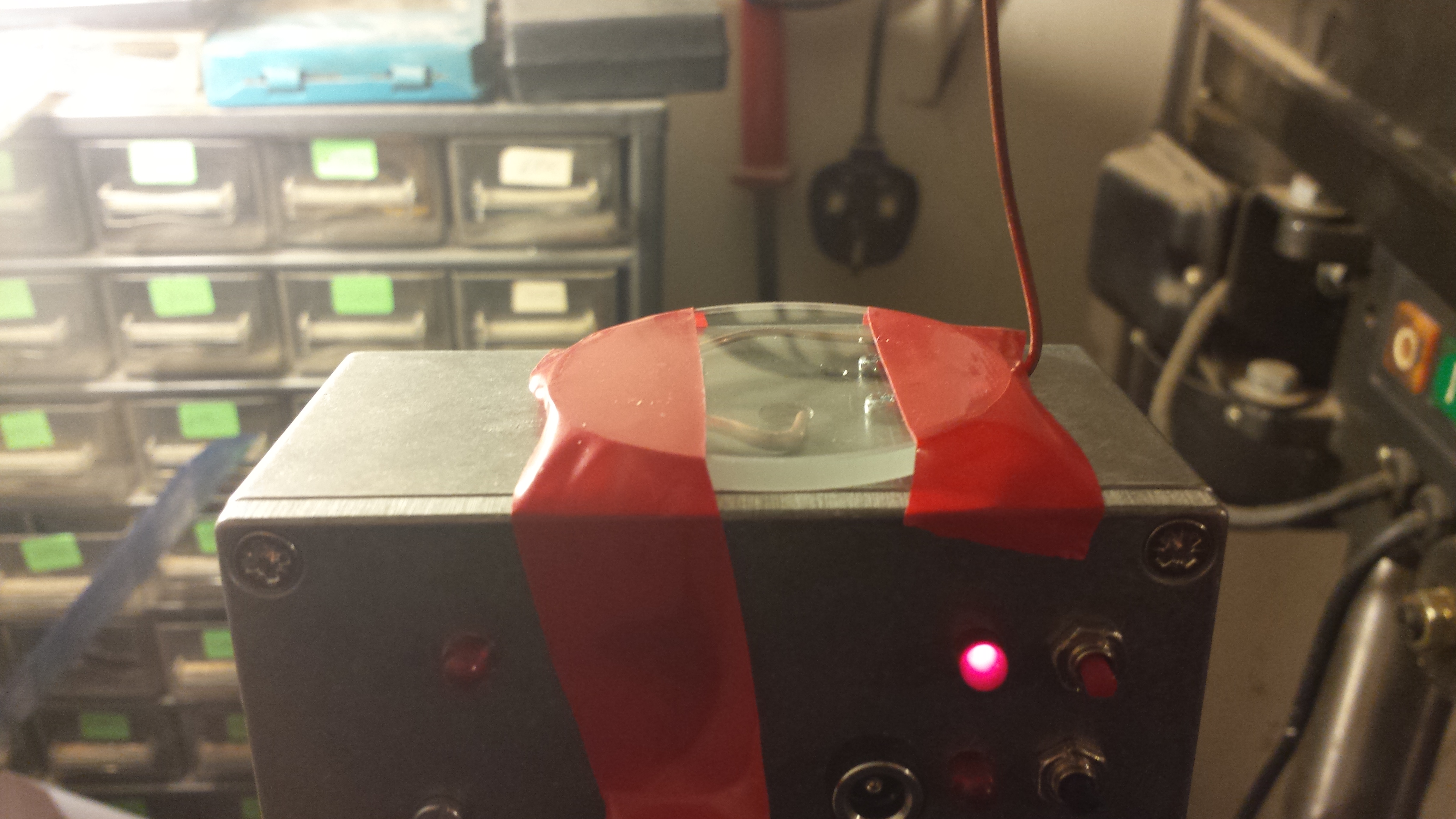
So I needed to get a better Tesla coil Tuner. I have been using this NE555 pinger for 10+ years.

Always said I’d put it in a box.. Never happened…

With some of the tuning problems I’ve had recently I needed a better solution.

So..


PIC powered USB controlled Tesla Coil Tuner using AD9850 DDS Frequency Synthesis.

Built on a PIC low pin count, USB development board (hence redundant RS232 connector)

Direct connectiontctuner to the Primary Coil with current measuring.

Three ways of measuring.

Primary and cap on its own(Secondary removed)

Secondary on its own (driven by primary with no Primary cap)

Primary Cap and Secondary (across spark gap) – Should see both current dips.


Tesla Coil Tuner - sec only

First plot of a small Secondary coil, using VB to drive the USB.

Plots at ~15 seconds for 1000 points (e.g will scan from 500Khz to 1.5Mhz in 1khz steps in ~15 seconds.)


Range 50Khz to 4Mhz (with some droop at each end)

I’m having some issues getting a plot with just a primary coil, not sure why at the moment. Also my driver (tc428) is damaged, its not driving correctly to ground. Which may be causing me some issues. But not bad for a first go.

More developments

Added an Ariel input (B)

Improved the display, and removed a whole load of noise on the traces.

Also, added the ability to take snapshots of the traces (pale colours) so you can see any change from scan to scan

Tesla Coil Tuner - sec-pri
This shows a current scan in Dark blue, with a snapshot in light blue and the Ariel input in dark green with a light green snapshot. The current scan was done with my hand near the topload hence the lower resonant frequencies.

This clearly shows the primary (C & L) as a large dip on the left and the secondary / topload as the smaller dip on the right. I’m feeding the primary coil and primary cap in parallel as this gives the best indication of the current change in the primary. For some reason driving the coil with Cpri in series shows a lumped resonance (or doesn’t show the primary resonance up at all)

EMPi – Raspberry Pi

A raspberry Pi that will stand the most intense electromagnetic and electro static environments and cope with EMP (Electro Magnetic Pulse). The sort of environment around tesla coils.


I started with a Pi and a Adafruit Pi-Plate. My first job was to create a optic-fibre link (115Kb/s) for comms to my tesla coils and it also doubles up as a remote and insulated tty console for the PI. The chips I used for the fibre are the Avago 1524/2524 1Mb/s fibre transmitter/receiver.

20140801_132030 20140801_132520


The transmitter is driven from a Microchip TC4428 which takes the 3.3v TX to 5V and gives the current drive for the TX LED .The RX is level shifted and inverted using a BC337 (update – a speed up cap was added to the base as at 115kb Rx errors were seen)


Img_20140815_3184 Img_20140815_3182


I realised that the Pi would have to run on its own power supply, so 6 rechargeable AA cells giving 7.2V were added, along with a 7805 regulator to give 5V for the Pi and a couple of diodes to allow the batteries to smoothly take over when the external power was removed.

As the power connector is open to the EM noise on the out side of the case, there is a diode , a cap and a 30V TVS across the power input.

It also became apparent that there was no way of cleanly switching off the Pi without connecting a network or terminal. So I added a button and a script to shutdown the Pi (although not cut the power).

A Pi Cam was attached and bolted to the case, A small hole lets it see the outside world without letting in too much radiation. I also added in a sedcond button which allows the camera to be turned on and off. The script makes the camera take photos every 10 seconds. (I hope to add video too)

Img_20140815_3190

Img_20140815_3187


I added a removable panel that cover’s the USB, Ethernet and Fibre ports. This is not ideal as I can’t close it fully when I’m running on fibre.

I also added a shutter that goes across the external power/charging connector to further protect the circuits.

20140814_175821 20140814_181113


A quick test proved that the Pi can run when sat on top of a small tesla coil.


Img-2014-08-14-173A11a Img-2014-08-14-173A10a


The camera also worked, but the breakout was too close for the camera to give good photos.

20140814_204123


A monocle (50mm lens with 50mm focal length) was added


Img-2014-08-14-19-3A41a


Img-2014-08-14-19-A30a


Giving a couple of goodish photos of the discharge from under the breakout point. (breakout is the wiggly black line to the LHS)

https://www.extremeelectronics.co.uk/empi-cambridge-teslathon-2014/

https://www.extremeelectronics.co.uk/tesla-coil-slow-motion-video-using-a-raspberry-pi/