The Gaussfest moved to the London Museum of Water an Steam this year.
A big thank you to the museum for hosting us, their volunteers and all of the coilers that supported us.


The Gaussfest moved to the London Museum of Water an Steam this year.
A big thank you to the museum for hosting us, their volunteers and all of the coilers that supported us.
I recently came across the book Electrostatics by A. D. More online which featured a modern (1975) electrostatic generator called the Dirod Machine.

This is the same book that I got the idea for the folded shakesphere machine, that works in a similar way to the Dirod machine.
The images in this book online were hard to make out, so I’ve been waiting to get hold of an actual copy of the book and until recently they have been extremely expensive.
I now have managed to get a copy of this book without a leg or arm sacrifice, so the build begins.
The Dirod machine is an influence machine similar to a Wimshurst machine, but instead of sectors it has rods, and only one rotor. In many ways it is the reverse of a Franklin motor explanation here .
The rough diagram for the machine

and a 3d view as the basis for the one I built.
Operation
The Dirod machine consists of a rotating ‘drum’ made from an even number of rods held in place by a pair of acrylic disks that rotate on a central shaft.
At each side of the “drum” is a conductive plate with a brush that lightly touches the rods as they move past. These plates will become charged as the drum revolves, and the charge from the rod is added to the charge on the charge collector as the brush contacts it. The charge collectors on both sides of the machine is where the output is taken. As the machine is symmetrical, the polarity of the charge building on a specific plate entirely depends on start conditions. Any residual charge imbalance is just amplified by the machine.
As the machine is mostly made of insulators, there is always some charge (however small) to stat this multiplication process.
Moving with the direction of travel of the rods from the charge collector, the rods pass under an inductor plate that is electrically connected to the charge collector and the rod is earthed by a neutralising brush that discharges the rod, by shorting it to the diametrically opposed rod that will have an equal, but opposite charge.
After the rod has been neutralised it will gain a charge from the inductor above by electrostatic induction, this will be of an opposite polarity to the inductor. The now charged rod will continue around to the opposite charge collector, sharing its charge and completing the cycle.
As the rods under the inductor become charged with the opposite polarity to the inductor, a voltage equal to the output of the machine will develop, this can be in order of 200Kv. To prevent this from arcing and shorting the machine, a shield is needed to prevent the charge on the rod from arcing to the inductor. This is achieved by a shield of acrylic between the rod and the inductor. As 200Kv can jump 60mm or more across a surface this shield needs to extend a long way past the inductor.
The “drum” of rods has a central axel and is mounted on two ball bearing races, and is driven by a 300RPM geared motor with a speed controller.
Construction
For my Dirod machine I chose 200mm long Aluminium rods. Each rod needs the sharp edges at the ends smoothing off, and a rubber cap gluing on to reduce the leakage from corona.


24 of these were glued into place on to two 3mm laser cut 150mm discs of acrylic. Which were attached to a central 6mm stainless steel axel with 3d printed bosses.


The Charge collectors and the inductors needed to be quite thick, and rounded to reduce corona leakage, so were 3D printed and covered in foil.


The Charge collectors differ to the inductors in two ways, one they have a 6mm hole in the top for the connection to the discharge balls, and they have a brush to collect the charge in the centre.


Initially I had all of the brushes made from brass shim, but after a short amount of usage i noticed that they were work hardening and starting to fail. Eventually I replaced them with conductive cloth backed with a strong repair tape. This gave them enough spring to connect with the rods as they went past with enough flexibility not to impede the rotation of the “drum”


The cloth brushes were also used on the neutralisers. Each nutriliser consisted of a 50mm stand-off with a brush glued in to place, connected through the end Acrylic to an aluminium coated bar that goes around the central shaft. All of the brushes were trimmed to contact the rods for only half of their diameter to limit the amount of movement required as the rods passed.


The Collectors and the inductors were glued into place on to the acrylic frame. The connection between the collectors and inductors was with a 3d printed element coated in foil, to ensure the minimum diameter of 12mm was maintained.


To prevent the insulation of the acrylic frame by conductive screws, the whole assembly is held together with acrylic wedges. The charge collectors (left and right) sit on the inside of the frame, whilst the inductors (top left, and bottom right) are glued to the outside of the much larger acrylic sheet, so this also acts as the shield.
Also note in the image above the neutralising bar has been reduced to maximise the stand-off voltage )in operation.
Two 6mm rods were bent over at 90 degrees and have 25mm balls to use as discharge balls. The rod is covered with PVC pipe as its diameter is too small to prevent a large amount of corona leakage on their own. The rods are loose in the charge collectors to allow for the gap between balls to be changed.


The “drum” is driven by a 12v 300RPM motor from a 12V source (usually a battery) To regulate the speed there is a speed regulator PCB under the motor. The motor is attached to the central shaft by a universal joint and the shaft sits on two flanged ball bearings attached to the acrylic frame.
Amazingly it worked first time, Even turning the “drum” by hand produced noticeable electricity.
It maxes out at about 60mm sparks, in really dry conditions. which relates to about 180Kv which is really not bad.
Dirod v Wimshurst
Comparing a 300mm Wimshurst machine with a 150mm x 200mm Dirod machine.
| Dirod | Wimshurst | |
|---|---|---|
| Voltage | Higher, due to greater current | Lower, except in very dry conditions |
| Current | Much higher, but its physically larger | Lower, but smaller in size |
| Build Good points | The tolerances are less exacting, single axle drive make simple mechanics. | High voltage points are not near mountings, no part of the machine has the entire output across it. Easier to add capacitors |
| Build Bad Points | Bigger and relies on good insulation of shields, high voltage near mountings/base. A lot of work to prep rods. Double the number of Brushes, | Contra rotating disks difficult to drive. More exacting tolerances . A lot of work to prep sectors. |
| Rods v Sectors | Harder to clean, more noise when working , much harder on the brushes. | Brushes are harder to maintain. Sectors are easier to clean, |
| Efficiency (subjective) | More | Less |


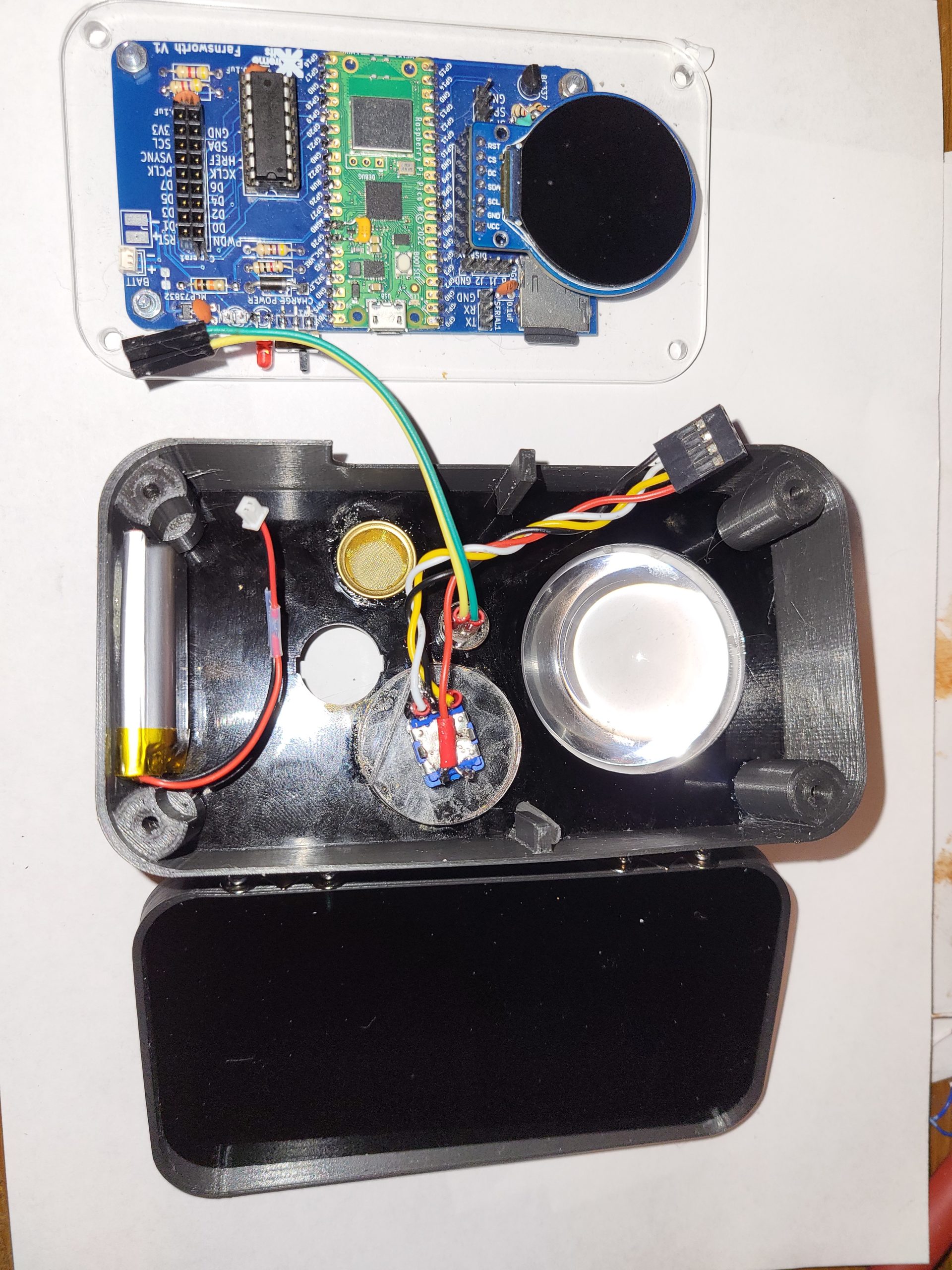
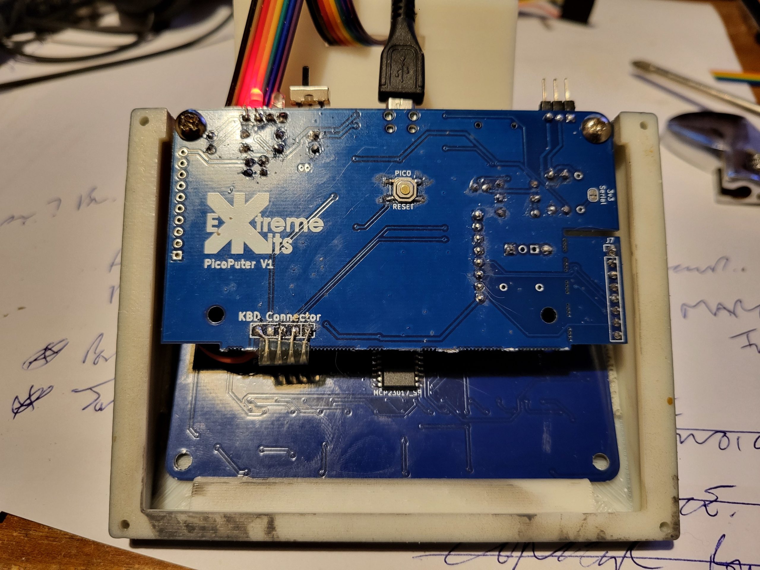
From the last post a lot has changed.
I’ve resized the cases and moved some of the aesthetics around to get every thing to fit in the case.
The display now gives connection information and displays status connected/not connected, and has the ability of displaying graphics with this information.
The software has had a lot of additions, I can now read from the SD card a set of destinations and select them using the rotary encoder wheel on the front of the case.
A destination is defined as an IP address, port and channel. The Channel is used by the UDP repeater to join Farnsworths together (Strowger.py)
The connection has gone from just Farnsworth to Farnsworth, to connection options using a central UDP proxy, (Strowger.py) hopefully with the aim of getting communication out from only being in the local network. This has also added various testing additions along the way including a test card and a loopback mode, both locally in the Farnsworth and to/from the proxy for remote testing.
If you have multiple Farnsworths on a local network, they need to be set to different ports so NAT can find them for the incoming channel.

Audio is proving to be a pain. The Pico’s A2D is very noisy, and the simple amp I put on the existing PCB isn’t up to the task to overcome this. I’ve replaced the single transistor amp with a low voltage op-amp that will hopefully have a lower output impedance into the ADC.

The other issue is ensuring that the 8khz sampling and playback happens regularly regardless of the camera’s capture and incoming UDP connections.
From comments from Mastodon, the two sound clips from the original Farnsworth have been incorporated, with the “text” tone used to indicate that the Farnworth has connected to WIFI, and the “RING” tone used to indicate that a Farnsworth to Farnsworth connection has been made.
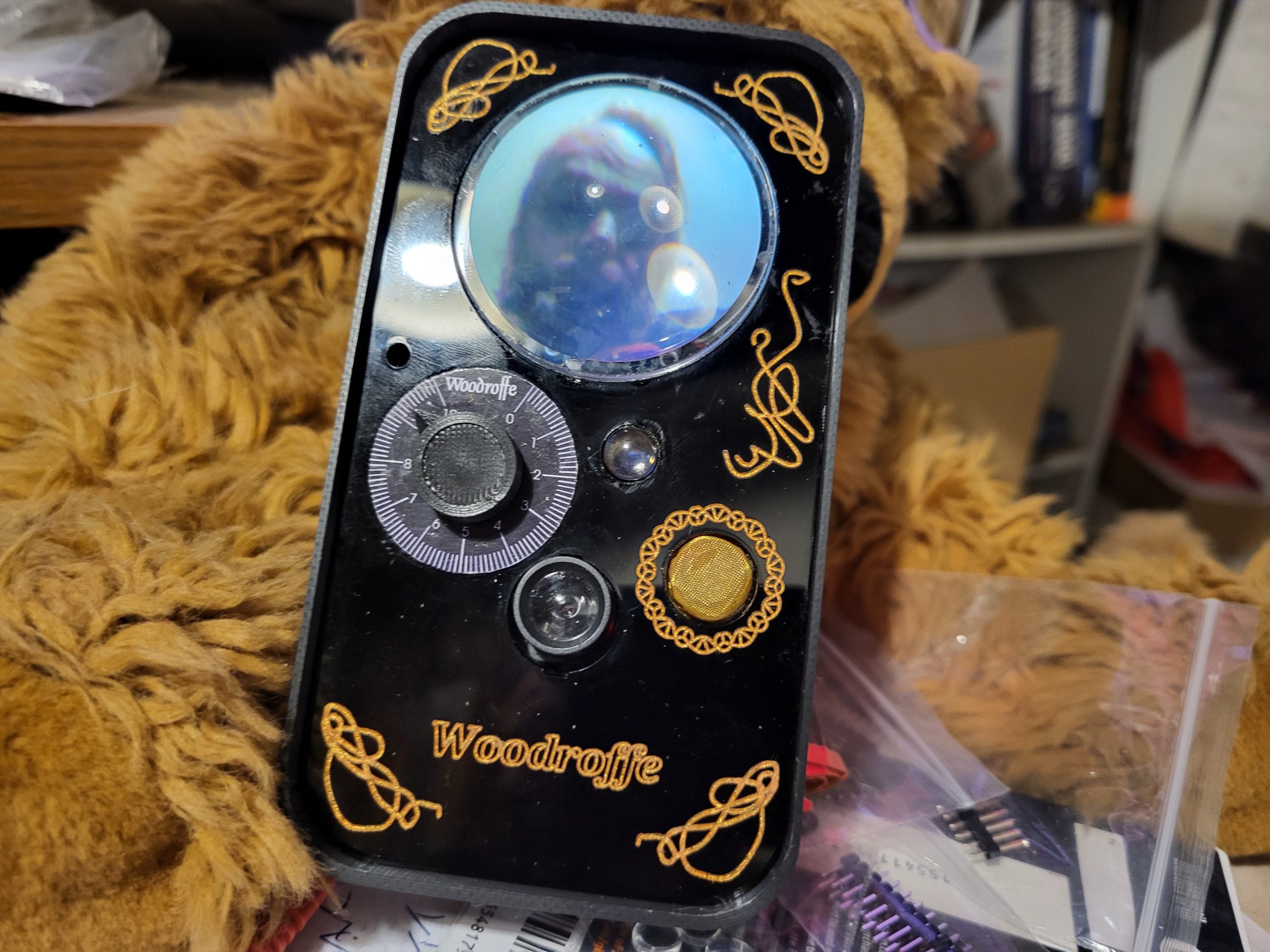
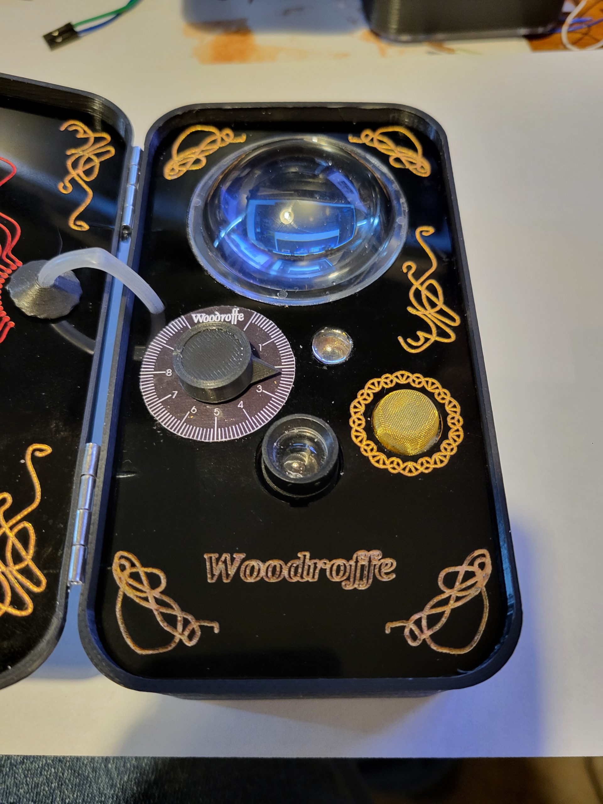
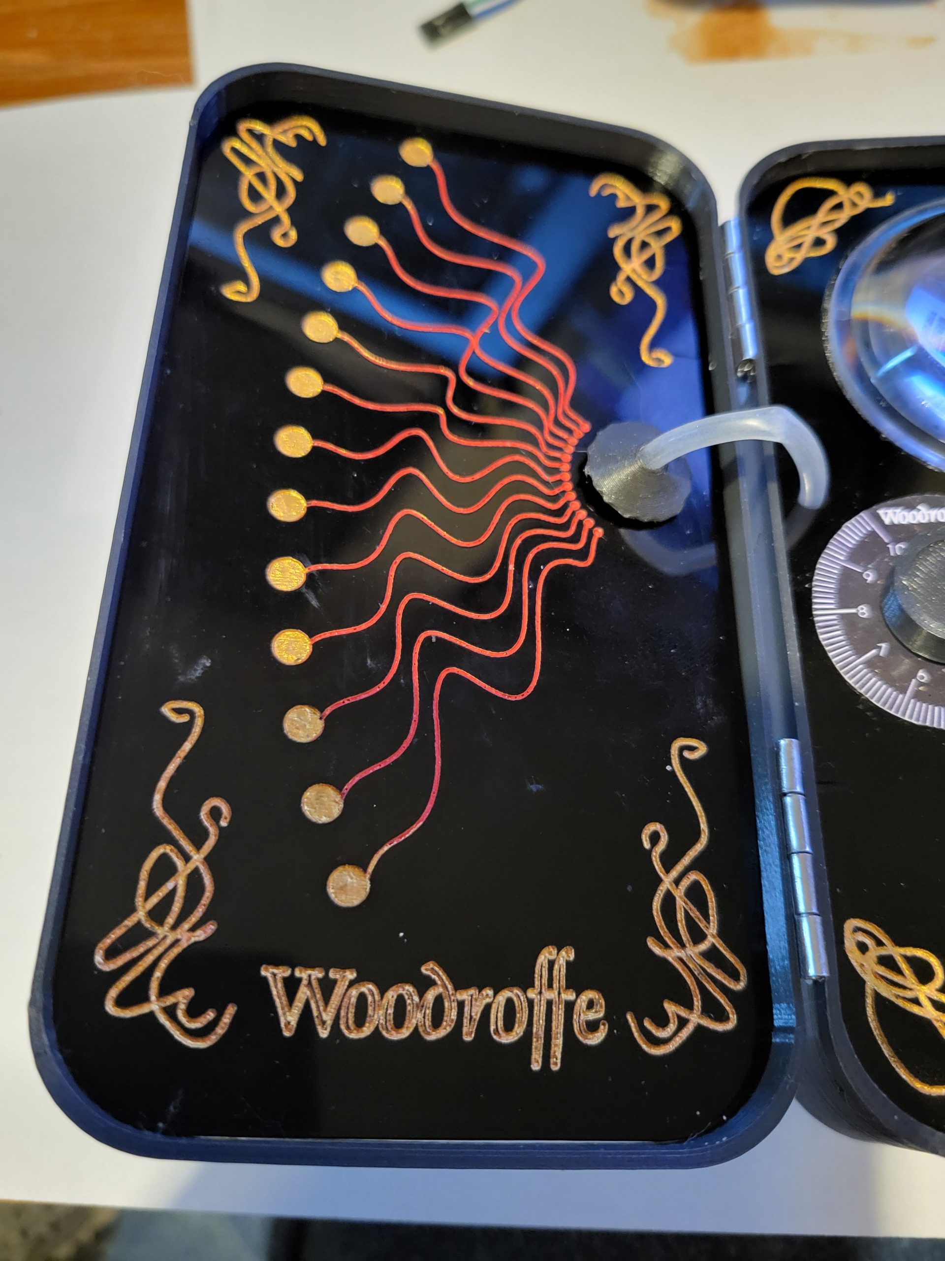
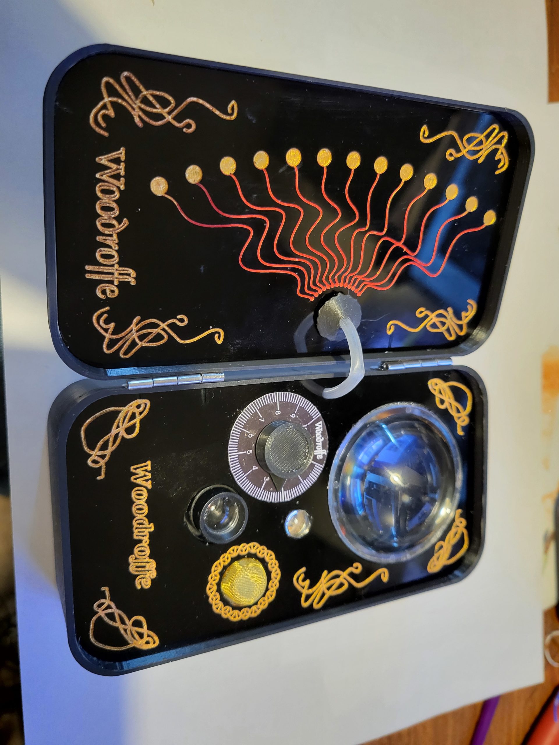
Finally got it all into the Case. This one is a Woodroffe, for obvious reasons for those that know me. When I get time ill update the older Farnsworth to the same case standard.
Just so happy I have two and they can talk to each other.
Code circuit diagram audio files and graphics are available on Github https://github.com/ExtremeElectronics/PhiloFax


So for reasons I’m not entirely sure of myself I decided I was going to build a Farnsworth.
For those of you who are not fans of Warehouse 13, as Farnsworth is a Steampunkesque hand held video and audio communication device, named after Philo Farnsworth the inventor of electronic Television.
A picture of one from the TV series is viewable on the Warehouse13 fandom site here
Of course this is only a prop, me, being me wanted one that worked.
“The Farnsworth is a two-way audio and video communications device invented by Philo Farnsworth in 1929, soon after the invention of the television. They’re used by Warehouse agents because they are on their own secure frequency spectrum and can’t be cracked, hacked, tapped, or otherwise “broken.” However, Artie stated in Season 5 that it could potentially be vulnerable to hacks if Claudia messed with it.”
My Farnsworth, will be totally hackable, insecure and very easily broken, but working. (hopefully)
Of course I could have just put a phone in a box and extended the display, microphone etc. but where is the fun in that ?
I’ve been playing with Pi Picos a lot recently, and Id not really explored the Pi PicoW and its networking abilities.
So all I need to do is to attach a camera, a display microphone and speaker and I’d be ready to go. Oh, and I didn’t want it to cost me an arm and a leg.
Looking in my spares box I had a cheap camera the OV7670, the problem with this device is, although cheap, it uses 14 IO, this would severly limit what else I could do with the PICOW. Luckily UsedBytes( Brian Starkey) https://github.com/usedbytes/camera-pico-ov7670 had done a pico project for robot vision using this camera, for this he had used a parallel to serial shift register to drop the 8 data lines to a single line and the PIco’s PIO to reconstruct the data. The downside was his library only ran at 80×80 pixels in mono.
After quite a lot of changing parameters in his library I got it to work dropping a 240×320 colour (RGB565) image into the Picos ram.
The Display was much easier, the GC9A01 35mm circular display is much more common, and as all I needed was to be able to write bitmaps to the display, I soon had cut down the available librarys and had a DMA running to drop the camera image to the display.
As I only wanted 240×240 on the display, I split the process into lines, rather than moving the whole buffer at once.
This also meant that I could send this data easily to a UDP Socket on the PicoW. All I do is add the line number to the beginning 240 RGB565 integers, and send this as a UDP packet.
At the receiving end, I strip off the first byte and dump the rest directly into the display. If a line is missing or corrupt (this is UDP) it gets over written in 1/5 second anyway.
This scheme also left me with 241-255 as a starting byte I could use for other purposes. Sound being one of these.
Sound is via a single transistor amp (probably needs to be a better amplifier) into the pico’s A2D sampled at 8Khz
So sound is given a starting byte of 250 and 10mS of sound is sent in the same way a line is sent every 10mS
At the other end the sound packet is unpacked and pushed into a FIFO buffer so it plays for 10mS, if the buffer empties then silence is played.
The Case outer is 3d printed from black PLA, and the two front plates are made from black acrylic engraved on a laser cutter with infill of acrylic paint.
Loads still to do, Ill update here as the project progresses.
The code is available on Github https://github.com/ExtremeElectronics/PhiloFax


Every year I make a badge for the Nottingham Gaussfest
Previous years I have just done a simple laser cut badge with a battery powered flashing LED, but this year I thought I’d do something a bit different.
My first idea was pushing the boat out a little too far, and after receiving the PCB’s I realised it would never work ( I don’t want to say what it was, as I have ideas for sort it in coming years)

So, as I was losing time quickly, I decided that I’d build a simple lightning detector. At the Gaussfest there are many, many machines that make sparks. So the idea was, when the exhibitors are making sparks, their badge lights up, what could be easier.
If I was going to do this, the badges MUST be there and working on the day. No point in having a lightning detector badge on a non-teslacoiling day.
I roughed up a circuit, based on Extreme kits lightning detector. To keep the LED on for a few seconds I used an NE555 timer.
The circuit was tested on bread-board and if I used a CMOS NE555 would run really well with a 3V supply. (Non CMOS 555’s need 6v AND take a lot more current)
I wanted to use through-hole as Extreme Kits’s lightning detector circuit used almost all of the same components but, I didn’t want ugly through hole wires on the front of the PCB, so I opted for through hole components, but surface mounted.

Happy with the circuit, I edited the PCB layout so I could get two boards in a 10x10CM order, which is the most cost efficient way of getting these PCB’s made with my supplier.
I also ordered 50 NE555 (CMOS) as the best prices came from china the PCB’s and the chips should arrive at roughly the same time.
After a couple of weeks the PCB’s and chips arrived and I quickly built one up and put in a CR2032 3v battery
It didn’t work, nothing…
Nothing I did would make it work, but everything seamed fine. Eventually I put it onto my PSU and tried it at 3V from there.
Nothing.
Scoping the output, it worked, but wouldn’t drive the LEDS, I tried every variation of LEDS I had, nothing worked (apart from a VERY dull glow).
On a hunch, I tried the circuit at 6V
Everything worked fine. Eh ???
I then occurred to me that my CMOS NE555’s (from China) may not be CMOS, I swapped one for a lone known good chip I had, the circuit worked fine. (insert swearwords here)
With not enough time to reorder CMOS 555’s, I needed a solution.

Well, CR2032’s are 3v and 3.2mm thick, CR2016’s are 3v and 16mm thick, I could fit two 2016’s in a 2032 socket giving me 6V. This worked, but the bottom battery would short. A small piece of tape sorted that quickly. The only down side now is that 2×2016’s have half the current capacity of 1×2032 and the non CMOS 555 chips are a lot more greedy. In a trial, the badges lasted 14 hours. I only needed them to last 8. I was hoping for a few days where I could put in the batteries and pack the badges. Adding a pull away tab which could turn them on, on the morning of the event sorted that. Finally I had a solution.

So, I built a batch of the PCB’s
Half of them worked, the other half refused to do anything. (insert other swearwords here)
On closer inspection the second PCB on each panel wouldn’t work.
Referring back to the PCB design I spotted my error, The fills would against ground, as I’d copied the PCB the signals for GND were no longer GND so the fills avoided the pads. All the GND connections were not connected. I didn’t have time to reorder the PCB’s
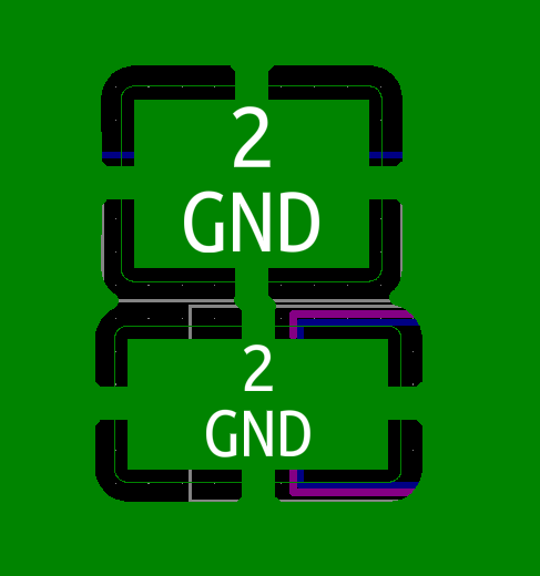

Luckily, my PCB house had done a couple of extra PCB’s, so I had JUST enough. The two organiser badges though, had a pretty addition of gold wires on the back joining all the GNDS together.

Finally a box of working badges, with only a few days to go. The only problem was I ran out of time, and I never got to test the badges with a real tesla coil or Wimshurst.

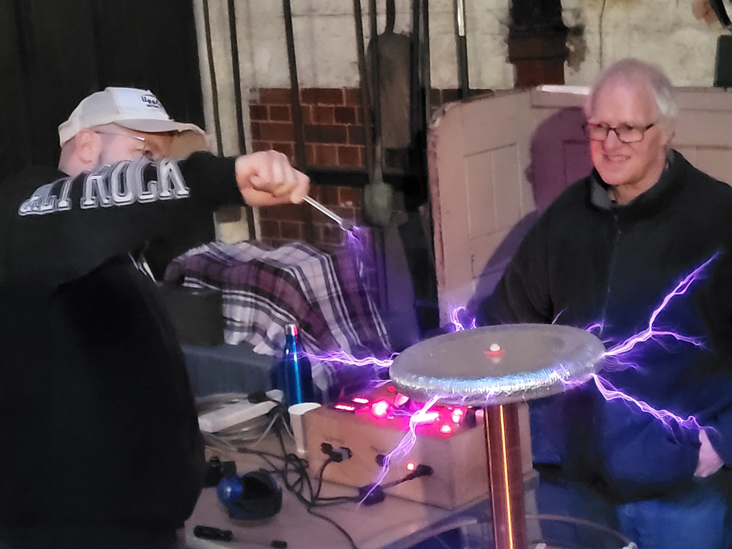
Luckily on the day they performed pretty well, If I was going to be harsh, they triggered occasionally on static discharges with peoples clothes, and their range was poor when they were close to the chest, but 1-2M away from my and other tesla coils they lit up wonderfully.
A badge being triggered by a discharge from my Shake sphere (that’s the background noise)
So my tips for designing a badge for an event.
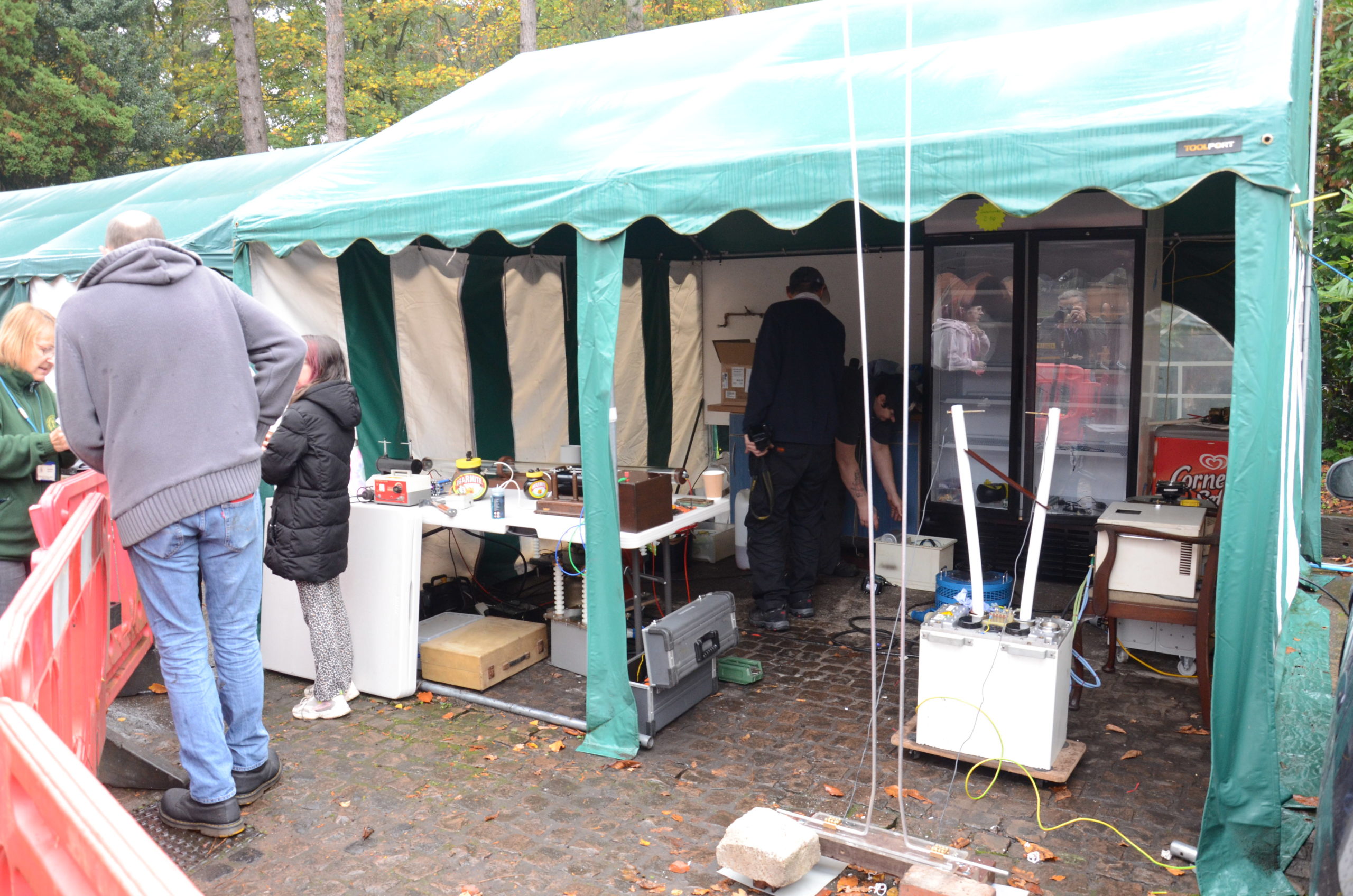
Another great day at Papplewick Pumping Station playing with all things high voltage. A very eclectic collection of high voltage exhibits again this year, and a big thank you to the exhibitors and visitors that literally came from all over the world to this event.
And of course a huge thank you to Papplewick Pumping Station and their volunteers for lending us their steam hall, boiler room and coal shelter for the day.
Here is a few photos and videos, Ill post more as I get them.


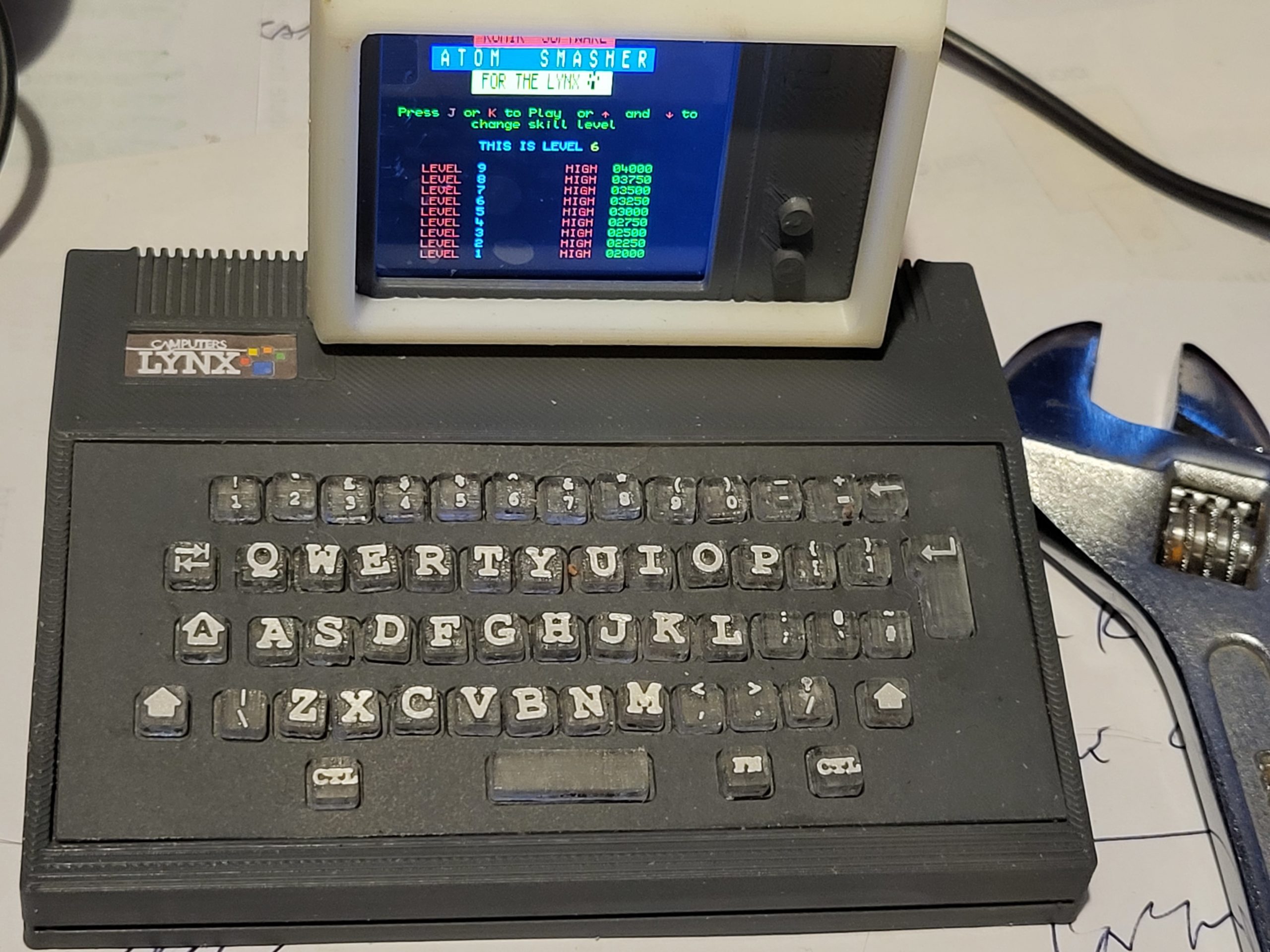
The Camputers Lynx was a classic, although not massively popular computer in the early 1980’s. It featured a z80 at 6Mhz and full colour graphics, with none of the BBC micro’s (or others) Graphics mode shenanigans. And for its time many advanced capabilities like 96K memory, a disk system (later upgradable to CP/M 80), and a proper keyboard. Unfortunately it hit at a bad time, the Spectrum was much cheaper, but much less capable, and the BBC was being pushed massively by the BBC (unsurprisingly). It’s eventual down fall was that its brilliant graphics were both quite slow and due to its strange memory banking system, rather hard to program. Eventually it lost out due to the lack of game titles compared to the Spectrum and BBC Micro/Electron.
But I had one and I loved it (latterly I had three)

I already have a PCB that Ive used for Pico Emulation of a number if things, so that was my go to as a start.
I had asked for permission to use the code by Charles Peter Debenham Todd retrogubbins (as there is no licence on his GitHub pages) and he graciously let me use his code with no restrictions.
I based my Pico design on his PALE emulator and his ESP 32 emulator https://github.com/retrogubbins/PaleESP32VGA
One of the first issues I had was that the Z80 emulation that he used did not have any licence either, so early on I swapped it to LIBZ80 © Gabriel Gambetta (gabriel.gambetta@gmail.com) 2000 – 2014 which is currently maintained by EtchedPixels as part of the z80 emulation kit https://github.com/EtchedPixels/EmulatorKit
I’ve used this library before in the RC2040 So familiarity was on my side too.

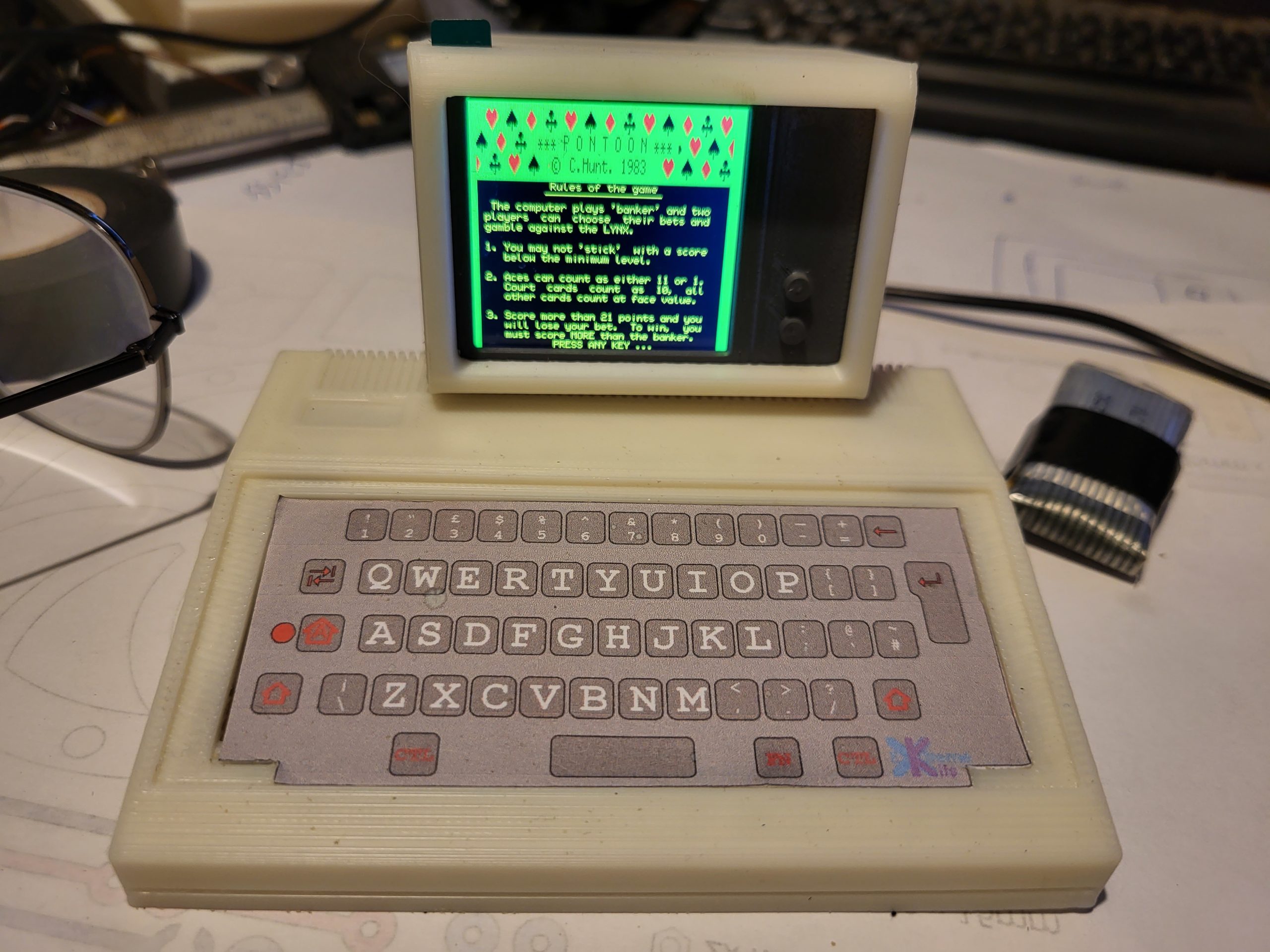
Swapping over the emulator and porting the ESP32 code to the Pico was amazingly straight forward, I needed to write some code to DMA out the RGB banks to a display (240×320 OLED) and I quickly got a Lynx prompt.

Unfortunately it was in Yellow, and the emulation stopped there. I took me a while to get past this, until I realised that the Lynx Beeps, between writing the Red and Green banks, and before writing Blue. I hadn’t implemented the code for the sound / speaker.
Adding this in gave me not only a while logo, but two power up beeps, and (after spanering in serial to the keyboard emulation ) a workable basic.

So time to make a case.
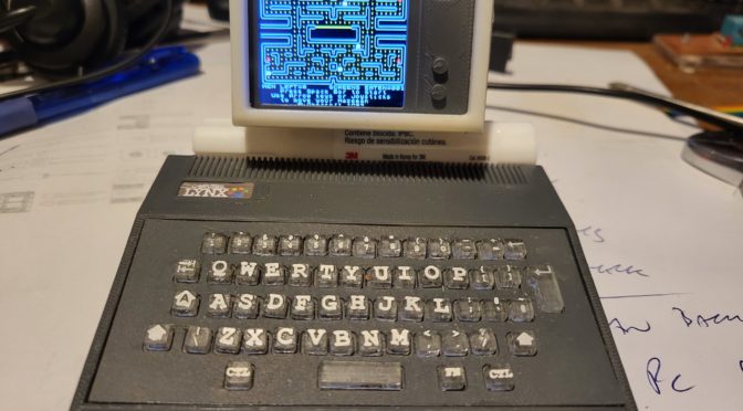
I took the measurements from a real Lynx and scaled it to roughly fit the keyboard I had with the PicoPuter. It came out as roughly 1:3

Of course Not everything fitted correctly, so after a few goes.

I got one that fitted and held the PCB’s in roughly the right place.
Of course I needed a monitor, so I did a quick 3D print of an IBM 5151 style monitor. This gave me the space to the right to hide the display connector. and as the original was only 12″ didn’t look out of place with the small Lynx Case.
For the keyboard I wanted actual working keys.
So I made an escutcheon from grey sprayed card

and laser cut/engraved a set of small keys to fit. Because I couldn’t get grey acrylic I used transparent acrylic, on top of a grey sprayed key holder.

The effect is grey keys with white painted idents.
Not 100% happy with these, but I have a set for working grey keys, on a grey Lynx shaped case. For a more accurate layout I’d need a custom Lynx keyboard PCB.
The whole case is only 120mm wide to give you some idea of scale.
The two PicoPuter PCB’s sit inside and a small battery, because it was vital for this to run as a portable 🙂
The Ribbon cable is the feed to the display, which is mostly hidden by the case and the display itself.

and attached to the back of the display by a small daughter board.
What is a Gaussfest ?
Nottingham Gaussfest is a yearly meeting of a loose group of friends sharing a common interest in high voltage equipment and Tesla coils.In the USA these meetings are always referred to as Teslathons, a reference to Nicola Tesla who’s tesla coils always feature prominently at these events. We decided, being European, we would adopt Carl Friedrich Gauss as the scientist, due to all the devices also required a high magnetic field and we wanted to differentiate ourselves. Hence the term Gaussfest.

The equipment that appears at the Gaussfest is entirely dependent on the Exhibitors present, and their current interests. Usually there will be a collection of various types of Tesla coils, and a collection of static electricity generators like Van-De Graff machines and Wimshurst machines. But each year someone surprises me with something different, or new.
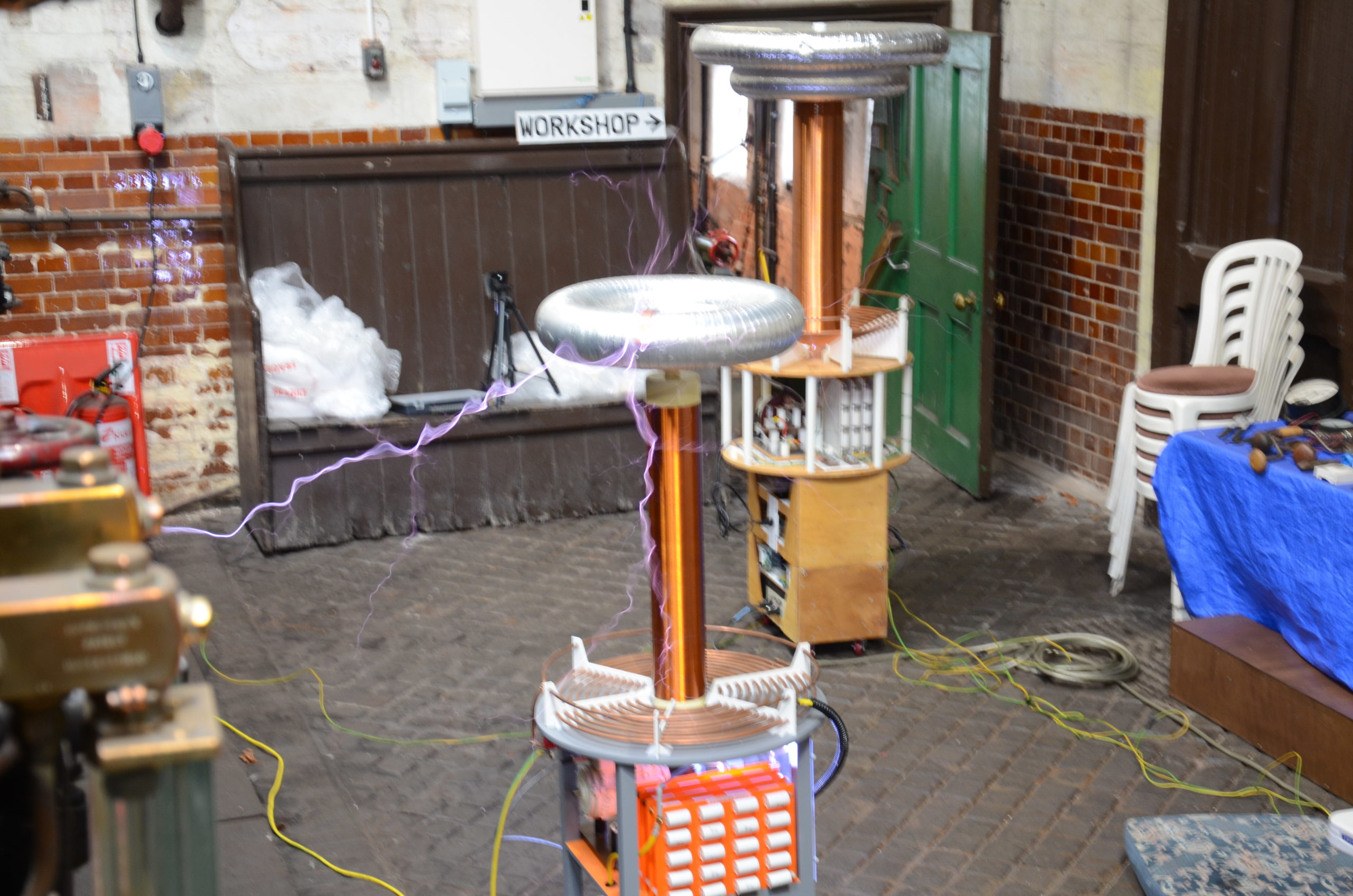
Tesla coils are the most common high voltage device we get, are essentially a large transformer. Near the bottom of the tesla coil is a radio frequency generator either electronic or mechanical, driving a primary winding with a small number of turns. The Secondary coil (the tall one) has a much larger number of turns of around 800-2000 turns typically. And at the top if this, a topload where the high voltage comes out. We get tesla coils of all sizes from a 50mm high, to over 2M tall at the Gaussfest.

The Static generating machines our exhibitors bring are even more are varied. The common ones are a Van de Graaff machine, uses a belt to transfer charge up to the top dome where it is stored, and the Wimshurst machine uses a pair of contra-rotating disks to multiply charge and store it into a pair of capacitors. Again the sizes of these machines vary from 200mm tall to 1.5MAlthough the electrical discharges from these machines look dangerous, they are entirely safe if viewed from a distance, and our exhibitors are very experienced with the operation of their machines.

Or Exhibitors are happy to talk about how their machines work and the problems with their construction, although if they are preparing them for a demonstration, or have problems please give them “thinking room” as their safety, and the safety of their equipment is paramount. All our exhibitors are all amateurs and make and demonstrate high voltage equipment for fun. The Gaussfest is their opportunity to display what they have been working on.

Commercial high voltage engineering is expensive, due to this many of the exhibits on display will have been made totally or partially from household items, surplus, and any available electronic equipment, often with items multiplied up to deal with the high voltages/currents that are required. To keep the cost down, the equipment is usually run at the very maximum of its tolerances. These devices are rarely engineered for their longevity, so failures are quite common, and this trade-off is very much part of the hobby. Due to this, we do not have planned schedules for the demonstrations, as equipment WILL FAIL (and be repaired) during the day, although we will endeavour to have something always happening.
When the Gaussfest moved to Papplewick in 2017, we were very conscious that for us to do our activities, Papplewick pumping station must get something back, So Papplewick allow us to meet, and we let the public see what we do and give demonstrations to give back to the Pumping station. As much of what we do can be dangerous, this trade-off is some restrictions in access to the station to ensure your safety.
A Hand held Electrostatic generator by A D Moore
In his book “Electrostatics; exploring, controlling, and using static electricity” A D Moore describes a simple electrostatic generator described as a shake sphere. Very little other information is given.
Luckily A.C.M. de Queiroz gives a simple description and picture of a built one here the operation is copied below.

Because I can never follow instructions and I always want to make my life harder, I deided to try to build a folded version. From the above it is reasonable to see that the earthed block in the centre is common so can be split, as long as its electrically re-joined.
This allows the inductors and collectors to be stacked next to each other rather than have a couple of trailing wires, and as the block is earth, then the wire joining these two blocks will be earth, much more efficient than two wires with high voltage. So I designed this.
The Collectors were 3D printed, then foiled and burnished to make then conductive. The two tubes are 200mm long and made from 25mm (OD) PVC electrical conduit. The two areas where the inductors would sit were taped. and 2 20mm steel balls were used as the charge carriers.

This was constructed and a simple test, with low humidity we could get sparks from the collectors after 30-40 rocks forward and back from the ball bearings.
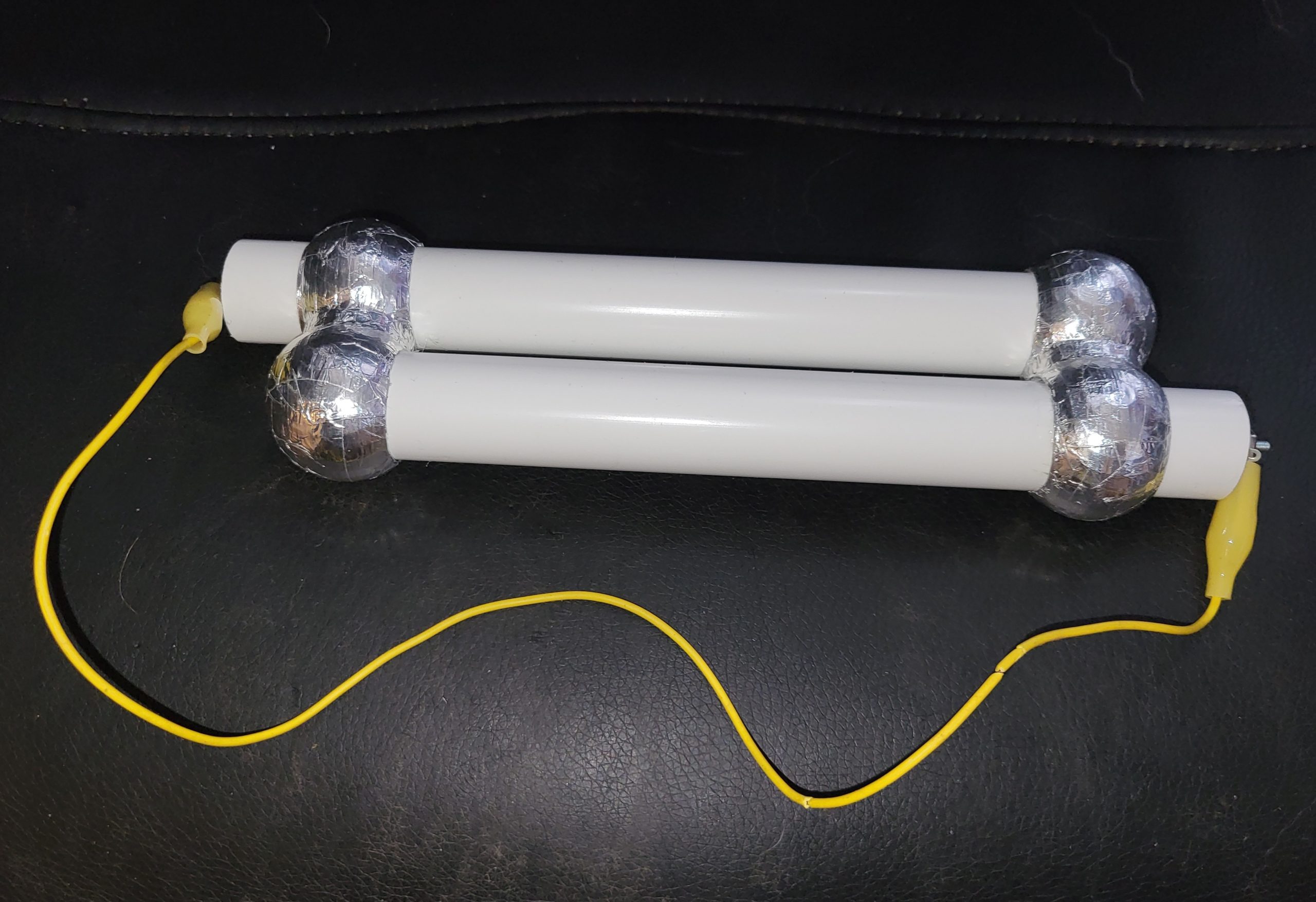

For ease of use, a handle was added and a couple of insulators to keep the earthed wire away from the charge collectors.
This will produce 10mm sparks on a good day, and is an interesting demo, but practically useless for anything else