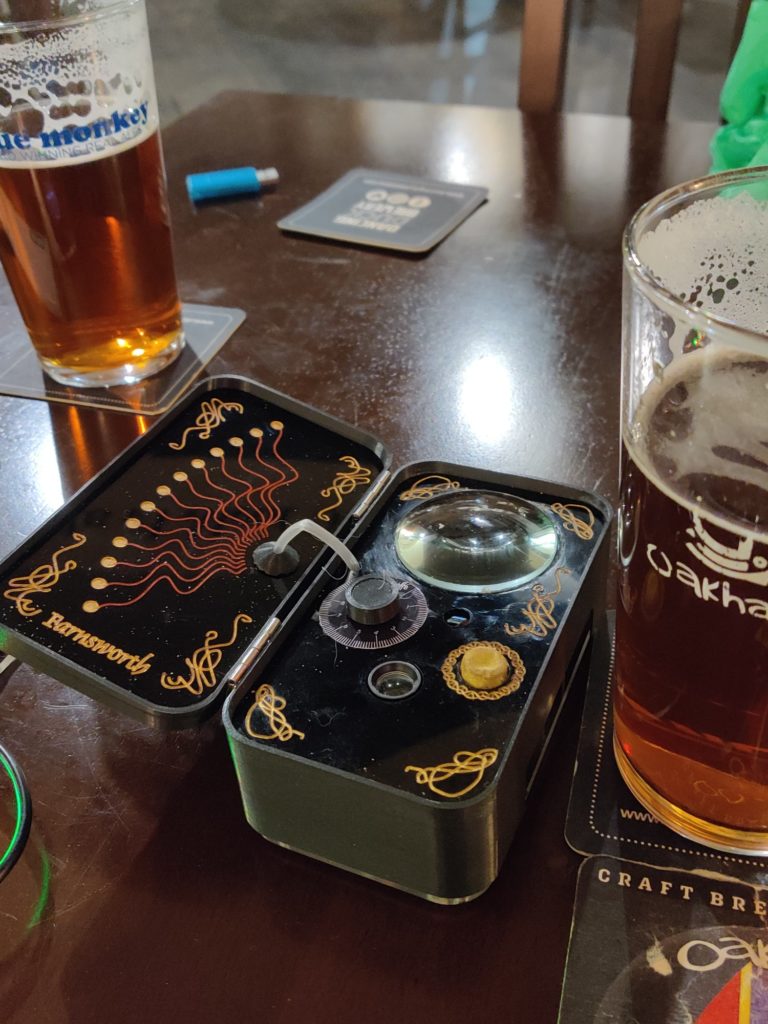
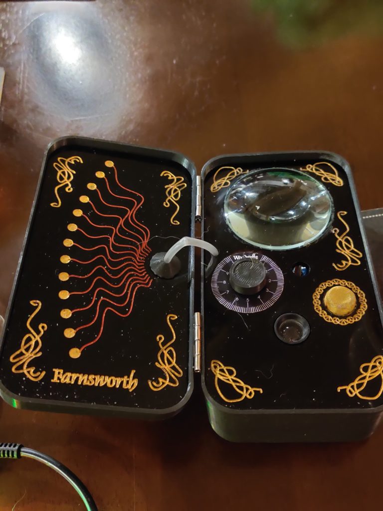
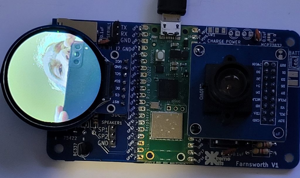
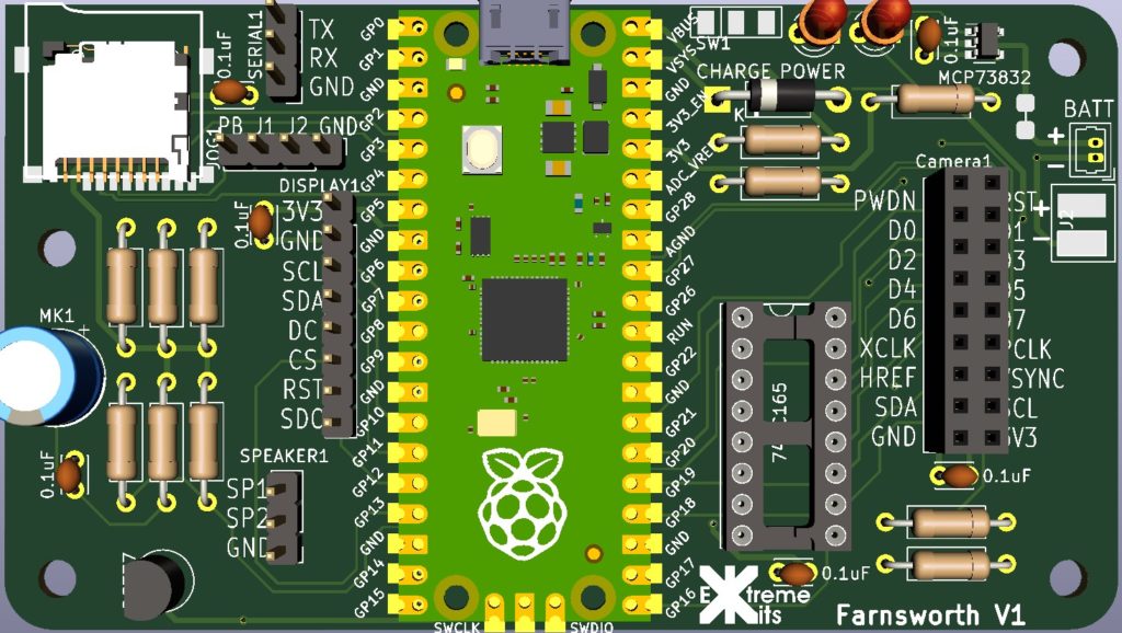
So for reasons I’m not entirely sure of myself I decided I was going to build a Farnsworth.
For those of you who are not fans of Warehouse 13, as Farnsworth is a Steampunkesque hand held video and audio communication device, named after Philo Farnsworth the inventor of electronic Television.
A picture of one from the TV series is viewable on the Warehouse13 fandom site here
Of course this is only a prop, me, being me wanted one that worked.
“The Farnsworth is a two-way audio and video communications device invented by Philo Farnsworth in 1929, soon after the invention of the television. They’re used by Warehouse agents because they are on their own secure frequency spectrum and can’t be cracked, hacked, tapped, or otherwise “broken.” However, Artie stated in Season 5 that it could potentially be vulnerable to hacks if Claudia messed with it.”
My Farnsworth, will be totally hackable, insecure and very easily broken, but working. (hopefully)
Of course I could have just put a phone in a box and extended the display, microphone etc. but where is the fun in that ?
I’ve been playing with Pi Picos a lot recently, and Id not really explored the Pi PicoW and its networking abilities.
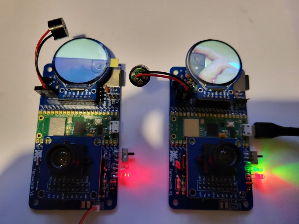
So all I need to do is to attach a camera, a display microphone and speaker and I’d be ready to go. Oh, and I didn’t want it to cost me an arm and a leg.
Looking in my spares box I had a cheap camera the OV7670, the problem with this device is, although cheap, it uses 14 IO, this would severly limit what else I could do with the PICOW. Luckily UsedBytes( Brian Starkey) https://github.com/usedbytes/camera-pico-ov7670 had done a pico project for robot vision using this camera, for this he had used a parallel to serial shift register to drop the 8 data lines to a single line and the PIco’s PIO to reconstruct the data. The downside was his library only ran at 80×80 pixels in mono.
After quite a lot of changing parameters in his library I got it to work dropping a 240×320 colour (RGB565) image into the Picos ram.
The Display was much easier, the GC9A01 35mm circular display is much more common, and as all I needed was to be able to write bitmaps to the display, I soon had cut down the available librarys and had a DMA running to drop the camera image to the display.
As I only wanted 240×240 on the display, I split the process into lines, rather than moving the whole buffer at once.
This also meant that I could send this data easily to a UDP Socket on the PicoW. All I do is add the line number to the beginning 240 RGB565 integers, and send this as a UDP packet.
At the receiving end, I strip off the first byte and dump the rest directly into the display. If a line is missing or corrupt (this is UDP) it gets over written in 1/5 second anyway.
This scheme also left me with 241-255 as a starting byte I could use for other purposes. Sound being one of these.
Sound is via a single transistor amp (probably needs to be a better amplifier) into the pico’s A2D sampled at 8Khz
So sound is given a starting byte of 250 and 10mS of sound is sent in the same way a line is sent every 10mS
At the other end the sound packet is unpacked and pushed into a FIFO buffer so it plays for 10mS, if the buffer empties then silence is played.
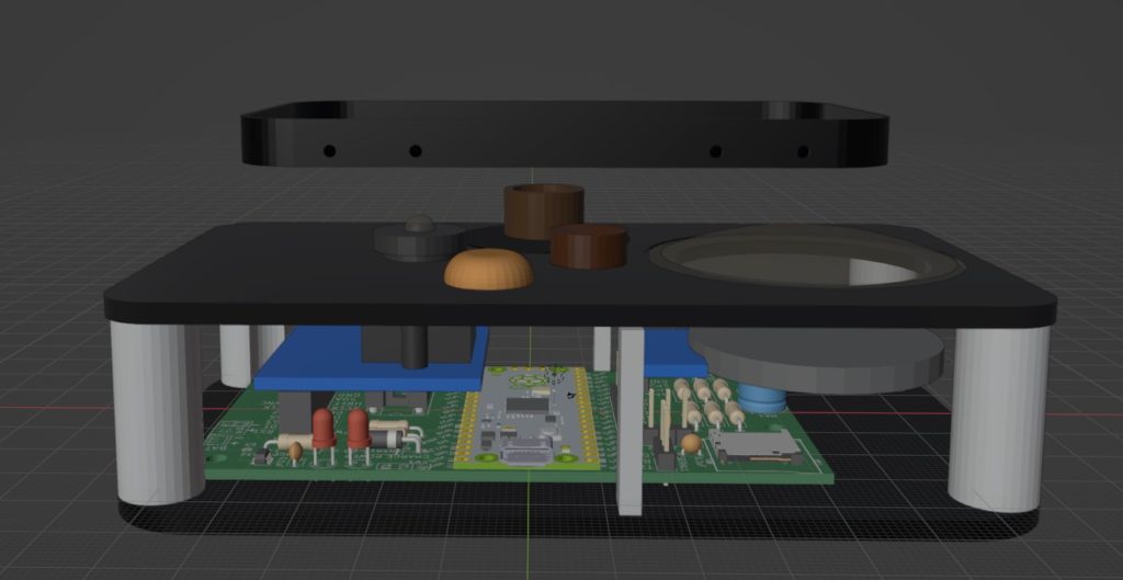
The Case outer is 3d printed from black PLA, and the two front plates are made from black acrylic engraved on a laser cutter with infill of acrylic paint.
Loads still to do, Ill update here as the project progresses.
The code is available on Github https://github.com/ExtremeElectronics/PhiloFax
