Category Archives: Raspberry Pi

Farnsworth (Warehouse 13) artifact creation

So for reasons I’m not entirely sure of myself I decided I was going to build a Farnsworth.

For those of you who are not fans of Warehouse 13, as Farnsworth is a Steampunkesque hand held video and audio communication device, named after Philo Farnsworth the inventor of electronic Television.

A picture of one from the TV series is viewable on the Warehouse13 fandom site here

Of course this is only a prop, me, being me wanted one that worked.

“The Farnsworth is a two-way audio and video communications device invented by Philo Farnsworth in 1929, soon after the invention of the television. They’re used by Warehouse agents because they are on their own secure frequency spectrum and can’t be cracked, hacked, tapped, or otherwise “broken.” However, Artie stated in Season 5 that it could potentially be vulnerable to hacks if Claudia messed with it.”

My Farnsworth, will be totally hackable, insecure and very easily broken, but working. (hopefully)

Of course I could have just put a phone in a box and extended the display, microphone etc. but where is the fun in that ?

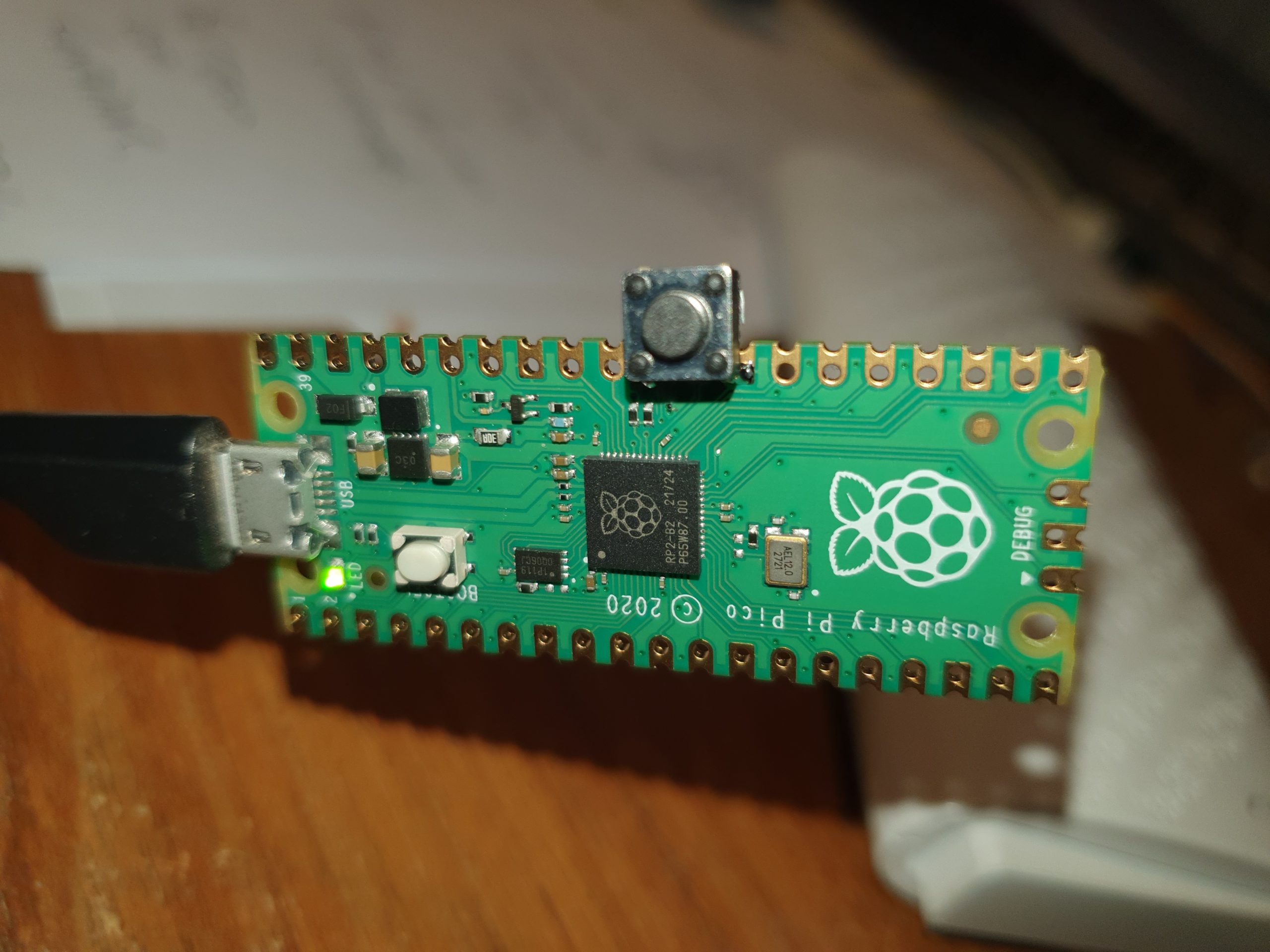
I’ve been playing with Pi Picos a lot recently, and Id not really explored the Pi PicoW and its networking abilities.

So all I need to do is to attach a camera, a display microphone and speaker and I’d be ready to go. Oh, and I didn’t want it to cost me an arm and a leg.

Looking in my spares box I had a cheap camera the OV7670, the problem with this device is, although cheap, it uses 14 IO, this would severly limit what else I could do with the PICOW. Luckily UsedBytes( Brian Starkey) https://github.com/usedbytes/camera-pico-ov7670 had done a pico project for robot vision using this camera, for this he had used a parallel to serial shift register to drop the 8 data lines to a single line and the PIco’s PIO to reconstruct the data. The downside was his library only ran at 80×80 pixels in mono.

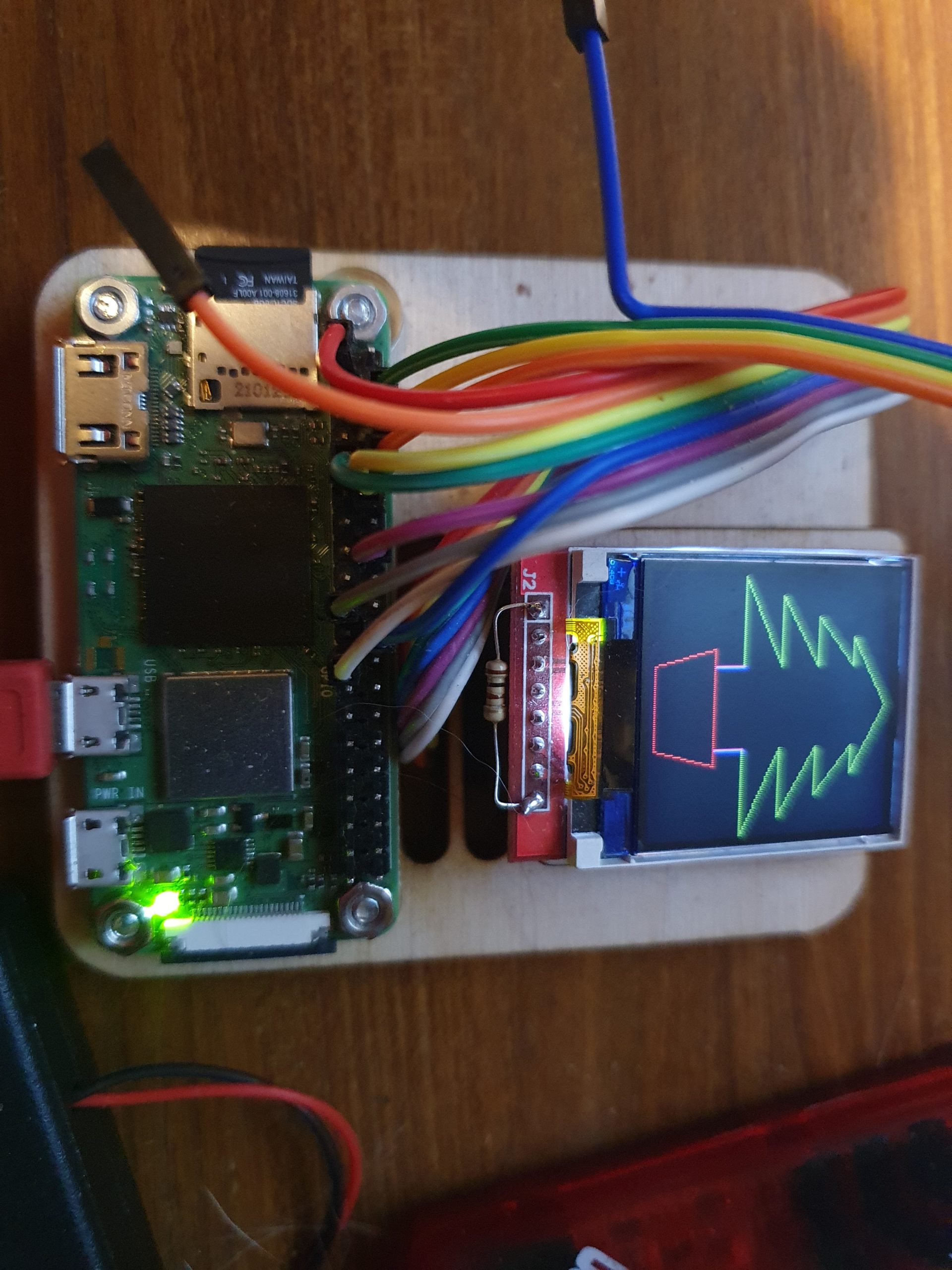
After quite a lot of changing parameters in his library I got it to work dropping a 240×320 colour (RGB565) image into the Picos ram.

The Display was much easier, the GC9A01 35mm circular display is much more common, and as all I needed was to be able to write bitmaps to the display, I soon had cut down the available librarys and had a DMA running to drop the camera image to the display.

As I only wanted 240×240 on the display, I split the process into lines, rather than moving the whole buffer at once.

This also meant that I could send this data easily to a UDP Socket on the PicoW. All I do is add the line number to the beginning 240 RGB565 integers, and send this as a UDP packet.

At the receiving end, I strip off the first byte and dump the rest directly into the display. If a line is missing or corrupt (this is UDP) it gets over written in 1/5 second anyway.

This scheme also left me with 241-255 as a starting byte I could use for other purposes. Sound being one of these.

Sound is via a single transistor amp (probably needs to be a better amplifier) into the pico’s A2D sampled at 8Khz

So sound is given a starting byte of 250 and 10mS of sound is sent in the same way a line is sent every 10mS

At the other end the sound packet is unpacked and pushed into a FIFO buffer so it plays for 10mS, if the buffer empties then silence is played.

The Case outer is 3d printed from black PLA, and the two front plates are made from black acrylic engraved on a laser cutter with infill of acrylic paint.

Loads still to do, Ill update here as the project progresses.

The code is available on Github https://github.com/ExtremeElectronics/PhiloFax

Continued here…

Pico Lynx

A Pico Emulated Camputers Lynx

The Camputers Lynx was a classic, although not massively popular computer in the early 1980’s. It featured a z80 at 6Mhz and full colour graphics, with none of the BBC micro’s (or others) Graphics mode shenanigans. And for its time many advanced capabilities like 96K memory, a disk system (later upgradable to CP/M 80), and a proper keyboard. Unfortunately it hit at a bad time, the Spectrum was much cheaper, but much less capable, and the BBC was being pushed massively by the BBC (unsurprisingly). It’s eventual down fall was that its brilliant graphics were both quite slow and due to its strange memory banking system, rather hard to program. Eventually it lost out due to the lack of game titles compared to the Spectrum and BBC Micro/Electron.

But I had one and I loved it (latterly I had three)

Camputers Lynx (By Retro-activity, CC BY-SA 3.0, https://commons.wikimedia.org/w/index.php?curid=31282859)

I already have a PCB that Ive used for Pico Emulation of a number if things, so that was my go to as a start.

I had asked for permission to use the code by Charles Peter Debenham Todd retrogubbins (as there is no licence on his GitHub pages) and he graciously let me use his code with no restrictions.

I based my Pico design on his PALE emulator and his ESP 32 emulator https://github.com/retrogubbins/PaleESP32VGA

One of the first issues I had was that the Z80 emulation that he used did not have any licence either, so early on I swapped it to LIBZ80 © Gabriel Gambetta (gabriel.gambetta@gmail.com) 2000 – 2014 which is currently maintained by EtchedPixels as part of the z80 emulation kit https://github.com/EtchedPixels/EmulatorKit

I’ve used this library before in the RC2040 So familiarity was on my side too.

Swapping over the emulator and porting the ESP32 code to the Pico was amazingly straight forward, I needed to write some code to DMA out the RGB banks to a display (240×320 OLED) and I quickly got a Lynx prompt.

Unfortunately it was in Yellow, and the emulation stopped there. I took me a while to get past this, until I realised that the Lynx Beeps, between writing the Red and Green banks, and before writing Blue. I hadn’t implemented the code for the sound / speaker.

Adding this in gave me not only a while logo, but two power up beeps, and (after spanering in serial to the keyboard emulation ) a workable basic.

So time to make a case.

I took the measurements from a real Lynx and scaled it to roughly fit the keyboard I had with the PicoPuter. It came out as roughly 1:3

Of course Not everything fitted correctly, so after a few goes.

I got one that fitted and held the PCB’s in roughly the right place.

Of course I needed a monitor, so I did a quick 3D print of an IBM 5151 style monitor. This gave me the space to the right to hide the display connector. and as the original was only 12″ didn’t look out of place with the small Lynx Case.

For the keyboard I wanted actual working keys.

So I made an escutcheon from grey sprayed card

and laser cut/engraved a set of small keys to fit. Because I couldn’t get grey acrylic I used transparent acrylic, on top of a grey sprayed key holder.

The effect is grey keys with white painted idents.

Not 100% happy with these, but I have a set for working grey keys, on a grey Lynx shaped case. For a more accurate layout I’d need a custom Lynx keyboard PCB.

The whole case is only 120mm wide to give you some idea of scale.

The two PicoPuter PCB’s sit inside and a small battery, because it was vital for this to run as a portable 🙂

The Ribbon cable is the feed to the display, which is mostly hidden by the case and the display itself.

and attached to the back of the display by a small daughter board.

Pico Cray – Small scale distributed computing.

The Pico Cray is a cluster of 8 Picos and a controller Pico. All Picos are connected in parallel by an I2C bus. The controller is designated by one GPIO being held low, the processor Pico’s addresses are allocated automatically. The Controller Pico has a 320x240px display connected by SPI and a couple of buttons. As all of the Picos run the same software updating the cluster is easy.

Currently the cluster is programmed to run a Mandelbrot program. With each processor Pico calculating 120 points before returning them to the Controller.

Pico Cray

Emulating a Z80 RC2014 with CPM and IDE drives via an SD card

The RC2040

Ive always loved Z80’s Even before programming in high level languages I was had compiling Z80 code on a Nascom1

Recently I’ve discovered the world of emulated Z80’s via the emulator written for linux by Alan Cox (Etched Pixels) (https://github.com/EtchedPixels/RC2014) This allows various configurations of Z80 RC2014 (https://z80kits.com) machines to be emulated (along with 8080 8086 and may other 8 and 16 bit processors)

My C code was rather rusty and I wanted a project to re teach me the basics.

Starting with the Etched pixels code I quickly got it running on a Raspberry PI Zero and added a few simple peripherals.

Z80 Emulated RC2014 driving a colour OLED display from BASIC

Which is all fine, but well it was, all a bit easy.

Not So easy

So, I was looking for a project to play with the RP2040, ideal, apart from The RP2040 doesn’t give a linux OS, It doesn’t have any storage (other than its own flash) and it only has 240K of memory.

To emulate a CPM system you need a minimum of 64K (plus a switchable ROM) some form of storage, ideally removable. Some way of loading the ROM (although this can be compiled in as an image) and a serial terminal.

Well the serial terminal is easy, there are 4 plus USB to play with, although all of the emulation uses STDIO uniquely, which is only partially supported on a PI Pico in C

As I was only interested in the Z80 bits of the emulation and only with the peripherals commonly supported on an RC2014. I started on the Raspberry pi, removing all of the other non z80 library’s and the other peripherals I wouldn’t need.

This was easy, rip a bit out, patch the code so it didn’t require it, edit the make file, recompile, test. Repeat until you have a basic Z80 emulated machine.

ROM/RAM

The ROM, I temporally coded into C via the linux xxd command, from one of the factory ROM’s available on the RC2014 git hub. https://github.com/RC2014Z80/RC2014/tree/master/ROMs/Factory

The next problem is that the emulator as configured uses 512K of ram (RC2014 – 512k ROM 512k RAM Module) to emulate a paged ram card. As the RC2040 only has 240K of memory I needed to remove the Ram/Ram paged memory code and replace it with a 64K ram/Rom paged emulation (RC2014 64k RAM Module and RC2014 Pageable ROM Module), that will only take at max 128K. It also must allow for the ROM to be paged out to allow the bootloader to be installed at 0x0000.

Using the compiled ROM I could easily fill an array of uint_8 with a ROM image, and switch using port 0x38 as a RC2014

CPM

CPM was emulated using the EtchedPixels code for a removable CF card. The Binary is readily available already configured to boot on an RC2014 again from the RC2014 git hub https://github.com/RC2014Z80/RC2014/tree/master/CPM

From the CPM source image (.img) file, you need to make an IDE file system onto a .cf file. using CPMtools. Details are towards the bottom of this page under “CP/M Application Disks” https://github.com/RC2014Z80/RC2014/tree/master/ROMs/CPM-IDE

Luckily this CF file can again easily be tested by loading up the image using the RPI z80 linux emulator.

SD Card

Of course the Pico doesn’t have any storage like a CF card and the 3.3v bus makes interfacing to a 5v CF difficult, but there is the possibility of using a SD card via SPI.

Luckily there is a library for SD cards which works with the PICO no-OS-FatFS-SD-SPI-RPi-Pico https://github.com/carlk3/no-OS-FatFS-SD-SPI-RPi-Pico

Working through the example was straight forward and gives a great way to test your SD card connections and if required, format a fat32 SD card.

The connections to the SD card are simple, 4 wires and power.

PICO Z80 Emulation test bed.

PICO or bust

At this point there is no way we can test the code on a RPI, so we need to dive into the PICO.

Compiling the code to the PICO without IDE support was surprisingly straightforward. All that was required was to replace the TX/RX STDIO calls with a call to the PICO UART. Unfortunately there was no easy non-blocking call to the receive queue using the USB serial. So initially the input/output was all via the hardware serial port.

I tackled the SD card next, making a simple bit of code to read a 64K rom image from the CD card directly into the ROM array, so I could remove the horrible compiled C ROM. The ROM images came directly from the RC2014 Factory ROM images on Git hub.

Buttons and switches

To make the ROM selection easier I added three switches to emulate the RC2014 A13, A14, & A15 ROM select jumpers, This meant I could easily switch between ROM starting addresses when loading from a rom image.

As I was adding switches, I decided to add a few buttons. which give me a Z80 reset and a dump RAM initially as a hex dump to the terminal, and latterly as a .bin file into the CD card for debugging.

To allow for a switch-less operation for the switches / buttons to work you need to ground GPIO 22, otherwise the RC2040 will run with switch-less defaults( currently CPM ROM and USB serial)

PICO CPM

I changed the IDE library to use the FatFS-SD-SPI-RPi-Pico file system and pointed it to load the .cf image from the card.

After A LOT of playing around with the differences in read/write and seek, plus RAM/ROM switching and serial problems. It finally loaded 🙂

I also found that if I disabled the RAM/ROM switching on a emulated z80 reset (from the button), I could warm boot into CPM, bonus…

Circuit

More Serial fun

Eventually I sorted the problems with the blocking USB serial by writing an interrupt driven routine that fills its own circular buffer, so now (from a switch) you can select which serial port you prefer.

Tiny Rc2040

If you don’t need the switches/ buttons, you can run it without, using a Pimoroni Tiny 2040 using the USB serial, making the smallest z80 CPM machine, ever (unless you know different?)

vbnvbn

Make your own

All of the files to emulate a Z80 with IDE on SD are available via git hub https://github.com/ExtremeElectronics/RC2040

Unfortunately I haven’t quite solved the Serial issues yet. The serial interface(s) will only take characters as a really slow rate. If you are going to cut/paste code into the RC2040 you will need to add in a 40mS (or longer delay) into your terminal program.

Serial issues are much improved. If added a block to the RX char circular buffer code that will only allow char RX, if the ACIA isn’t currently in an interrupt and added a fake interrupt to drive the USB RX circular buffer in the same way as the UART RX

Added SIO support and some bodges to delay the emulated interrupts to allow serial as fast as the Z80 emulation can cope with.

Using Terra term I can now drop files onto the RC2040 with only a 1ms TX delay.

Continued here

RC2040 Emulated RC2014 kit

PIZero Tesla Coils at the RI Christmas Lectures

Earlier this month it was my great honor to be invited to demonstrate the PI zero tesla coils at the Royal institution Christmas lectures.

The Christmas lectures were a Christmas institution when I was growing up and they formed a great part of my education, especially the ones by Eric Lathwaite. This year is their 80th televised Christmas Lecture, I’m sure in that time it has inspired the lives of many many children to investigate science, and long may it continue to do so.

Behinds the scenes at the lectures was incredible, the organised chaos that was happening was untrue. There were 20+ experiments in the lecture (the first of three) and moving them in and out of the theater was a very well choreographed scientific dance.

I have every admiration to the RI and Windfall Films that produce it.

Walking in to the theater and standing where Faraday and not to forget, Tesla himself had lectured, I can’t explain the feeling. Oh, and the 350+ kids watching you… No Pressure…

The theater is incredible, it’s so much smaller than it looks on TV, add three cameras, a lecturer and 10+ support staff (dressed in black), it doesn’t leave much room for demonstrations that need a couple of meters exclusion zone for safety.

What will be featured on the lecture on Boxing day, not a clue, as is usual with any filming, its down to the final edit.

Even if I don’t make it on to the show, watch anyway well worth it for kids of all ages.

Behind the Ri Christmas Lectures- Show 01, 2016 Mark Parker – Standup Maths (warm up guy)

This Lecture is the first to go out BBC4 20:00 Boxing day 2016

The video is now available at http://richannel.org/christmas-lectures/2016/supercharged-fuelling-the-future


Details of the PiZero Tesla coils 

RPI I2C interface to Microchip embedded uP – Clock stretching

If you are going to implement I2C to an embedded uP read this first http://www.slate.com/blogs/bad_astronomy/2016/03/28/psychedelic_stroboscopic_easter_eggs.html

If you are using a Microchip uP you might want to continue reading.

Here is the problem, Raspberry Pi’s I2C software can’t cope with slave clock stretching, not a problem if you can service the data request quickly, well you would have thought not anyway. Unfortunately Microchip’s hardware (using a PIC18F14K50 and many others)  always puts in a small clock stretch for a slave transmit, even if you disable clock stretching with the SEN bit.   A thorough read of the data sheet gives you a clue “The ACK pulse will be sent on the ninth bit and pin SCK/SCL is held low regardless of SEN“.

So data transmission TO the PIC works fine (if you can deal with the I2C data quickly enough), but for Slave data transmit TO the RPI you get errors. The problem is, they are random and depend on the exact timing of the I2C bus and uP speed.

This clock stretch only happens after the address byte and before the transmission data. It causes a short or missing clock pulse (as the RPI ignores the presence of the clock held low by the slave) as in the transition of bytes 3 &4  of data in the oscilloscope capture below.

DS1Z_QuickPrint7

So how do we work around this, well to be honest there isn’t a total solution. (that I’ve found) the best that I have achieved is to change the I2C clock speed  so the timing of a clock stretch happens when the clock is already low and tweak the uP interrupt software.

The clock speed change is unfortunately a trial and error process whilst monitoring the data (and probably watching with a scope). To change the I2C bus speed with a newer PI distro, you need to edit the /boot/config.txt and edit or add the line “dtparam=i2c1_baudrate=clockspeed” try clock speeds from 20000 to 400000 and follow by a reboot of the PI to make the changes active.

The bus clock speed that will work will vary with the microprocessor speed,  so there is no single solution. With my setup 200Khz and 50Khz works well (uP clock @32Mhz) where 400khz and 100khz is a total wright off.

I have also changed the I2C code in the PIC18F14K50 to give a fast set of the  BF flag after data transmission which helps minimise the clock hold time.

if (PIR1bits.SSPIF) {
      
        if (!SSPSTATbits.D_NOT_A) {
            //
            // Slave Address
            //
            i2c_byte_count = 0;

            if (SSPSTATbits.BF) {
                // Discard slave address
                sspBuf = SSPBUF;    // Clear BF
                SSPSTATbits.BF=1;
            }

            if (SSPSTATbits.R_NOT_W) {
                // Reading - read from register map
                SSPCON1bits.WCOL = 0;
                SSPBUF           = i2c_reg_map[i2c_reg_addr++];
              
            }

        } else {
            //
            // Data bytes
            //
            i2c_byte_count++;

            if (SSPSTATbits.BF) {
                sspBuf = SSPBUF;    // Clear BF
                
            }

            if (SSPSTATbits.R_NOT_W) {
                // Multi-byte read - advance to next address
                SSPCON1bits.WCOL = 0;
                SSPBUF           = i2c_reg_map[i2c_reg_addr++];
                SSPSTATbits.BF=1;
               
            } else {

                if (i2c_byte_count == 1) {
                    // First write byte is register address
                    i2c_reg_addr = sspBuf;
                } else {
                    // Write to register address - auto advance
                    //   to allow multiple bytes to be written
                    i2c_reg_map[i2c_reg_addr++] = sspBuf;
                }
            }
           
        }//else
        
        SSPCON1bits.CKP = 1;            // Release clock
        // Limit address to size of register map
        i2c_reg_addr %= sizeof(i2c_reg_map);

        // Finally
        PIR1bits.SSPIF  = 0;            // Clear MSSP interrupt flag
      
    }   

With these changes, I have got (as the adverts say) up to 100% TX from a slave without error. This is about the best we can do until either Microchip change their hardware, or RPI write a I2C handler that supports clock stretch.


Headless Raspberry PI (PIZero) setup

The PIZero Simple setup without network or monitor. (Requires some prior knowledge of RS232 adapters and serial port setup)

First start by getting a PI SD image I used Raspian Jesse Light https://www.raspberrypi.org/downloads/raspbian/

Install into a sd card and make sure it runs (green light at least)

With a 3.3v RS232 adapter connect earth and RX/TX to your PI. Be careful some adapters are only 5V and will damage your PI’s UART pins.

PiZero

Setup your PC (I use Tera Term) serial adapter for 115200, 7 bits, even parity, 1 stop bit.

Boot your PI

If you get a screen of gobbledegook then good, otherwise swap your TX and RX around. When the gobbledegook has finished, press return a couple of times, and you should get a login prompt.

For some reason the console and boot up output at different baud rates (Caused by auto baud rate detect, settings above amended so this shouldn’t happen now)

Configure your PI the usual way. You will need some network to get your updates, but apart from that you have a working PI.

If you are brave (or idle) you can connect the +5v line from your serial adapter to power your PI too so you don’t need another usb power lead. Just be very careful that you attach it to the correct pins, otherwise your PI will be damaged.


Useful links.

(although I found the baud rate setting wrong everywhere I looked. Either auto baud rate detect at work, or it changes from distro to distro)

Element 14 no display using the raspberry pi serial console

RPi Serial Connection


Update:

The baud rate is auto detected, the native speed is 115200 (amended above) The auto detection only happens at the login prompt. The auto detection won’t pick up changes in bits/stop bits/ or parity. You can change the console getty port/speed/parity settings look at RPi serial connection above.

WiFi

If you have a wifi adapter and micro USB to USB lead, you can connect to WIFI. After connecting via RS232 edit the file /etc/wpa_supplicant/wpa_supplicant.conf using sudo nano

add in the lines

network={
    ssid="Your_WIFI_SSID"
    psk="Your_wifi_password"
}

and reboot the pi sudo shutdown -r

re log in to the pi and type ifconfig to fins the wifi IP address. 
Then you can ssh to your PI and even better update the software.

Note : for Pi 3. You may need some changes to get the headless conf working, especially at non default baudrates, take a look at http://www.briandorey.com/post/Raspberry-Pi-3-UART-Boot-Overlay-Part-Two


I2C control of LCD Display using YwRobot LCM1602 V2 & Raspberry PI

Using the YwRobot to control a 20×4 line display via I2C on a Raspberry PI, what could be easier.
PI display
Well, If all of the code was only for an arduino and there being no actual documentation or wiring diagram. Note: Example code IS NOT documentation.

Hey Ho, After some playing around I found the pin arrangement


addr, en,rw,rs,d4,d5,d6,d7,bl
0x27, 2, 1, 0, 4, 5, 6, 7, 3

0x27 is the i2c port address (bus 1 on newer PI’s)

I found this code snippet for a different set of boards http://www.rpiblog.com/2012/07/interfacing-16×2-lcd-with-raspberry-pi.html which was near, but made the display backlight flash and no text output.

So the hacking started…

Basically all of the control lines were on different pins, and I needed to control the backlight (via a wrapper on the i2c write code)

pylcdlib.py
import smbus
from time import *

#
# Modified from http://www.rpiblog.com/2012/07/interfacing-16×2-lcd-with-raspberry-pi.html to run
# 20×4 line display with YwRobot LCM1602 IIC V1 backpack
#

# General i2c device class so that other devices can be added easily
class i2c_device:
def __init__(self, addr, port):
self.addr = addr
self.bus = smbus.SMBus(port)

def write(self, byte):
self.bus.write_byte(self.addr, byte)

def read(self):
return self.bus.read_byte(self.addr)

def read_nbytes_data(self, data, n): # For sequential reads > 1 byte
return self.bus.read_i2c_block_data(self.addr, data, n)

class lcd:
#initializes objects and lcd
”’
Port definitions
addr, en,rw,rs,d4,d5,d6,d7,bl
0x27, 2, 1, 0, 4, 5, 6, 7, 3

”’

def __init__(self, addr, port):
self.lcd_device = i2c_device(addr, port)

self.backlight=1; #default to backlight on

def lcd_init(self):
#set 4 bit mode
self.lcd_device_writebl(0x30) #write
self.lcd_strobe()
sleep(0.005)
self.lcd_strobe()
sleep(0.005)
self.lcd_strobe()
sleep(0.005)
self.lcd_device_writebl(0x20)
self.lcd_strobe()

self.lcd_write(0x28)
self.lcd_write(0x08)
self.lcd_write(0x01)
self.lcd_write(0x06)
self.lcd_write(0x0C)
self.lcd_write(0x0F)

#wrapper to self.lcd_device.write fir backlight control
def lcd_device_writebl(self,value):
if self.backlight:
self.lcd_device.write(value | 0x08);
else:
self.lcd_device.write(value)

# control backlight on=1 or off=0
def lcd_backlight(self,on):
self.backlight=on
self.lcd_strobe()

# clocks EN to latch command
def lcd_strobe(self):
#bit 2
self.lcd_device_writebl((self.lcd_device.read() | 0x04))
self.lcd_device_writebl((self.lcd_device.read() & 0xFB))

# write a command to lcd
def lcd_write(self, cmd):
self.lcd_device_writebl((cmd >> 4)<<4)
self.lcd_strobe()
self.lcd_device_writebl((cmd & 0x0F)<<4) self.lcd_strobe() # self.lcd_device_writebl(0x0) # write a character to lcd (or character rom) def lcd_write_char(self, charvalue): self.lcd_device_writebl((0x01 | (charvalue >> 4)<<4))
self.lcd_strobe()
self.lcd_device_writebl((0x01 | (charvalue & 0x0F)<<4))
self.lcd_strobe()
self.lcd_device_writebl(0x0)

# put char function
def lcd_putc(self, char):
self.lcd_write_char(ord(char))

# put string function
def lcd_puts(self, stringin, line):
if line == 1:
self.lcd_write(0x80)
if line == 2:
self.lcd_write(0xC0)
if line == 3:
self.lcd_write(0x94)
if line == 4:
self.lcd_write(0xD4)

string=stringin + ” ” #blank out rest of line
string=string[0:20];#limit lines to 20 char

for char in string:
self.lcd_putc(char)

# clear lcd and set to home
def lcd_clear(self):
self.lcd_write(0x1)
self.lcd_write(0x2)

def lcd_cursoroff(self):
self.lcd_write(0x0c) #cursor and blink off

# add custom characters (0 – 7)
def lcd_load_custon_chars(self, fontdata):
self.lcd_device.bus.write(0x40);
for char in fontdata:
for line in char:
self.lcd_write_char(line)