Static electricity doesn’t exist

Yes, I know, its was taught to you at school. Me too.  I even have a book that has separate chapters of static electricity and conventional current electricity. So what is the problem, well it took me years to work out that there is no such distinction. Its all electricity. Static electricity on the terminal of a VDG sphere doesn’t suddenly transform in to current electricity when it is discharged and current electricity doesn’t transform into static when its stored in a capacitor.. The same rules must apply to both.

To use the water analogy, water is the same if its in a lake or  in a stream.

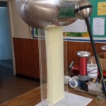
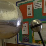
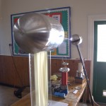
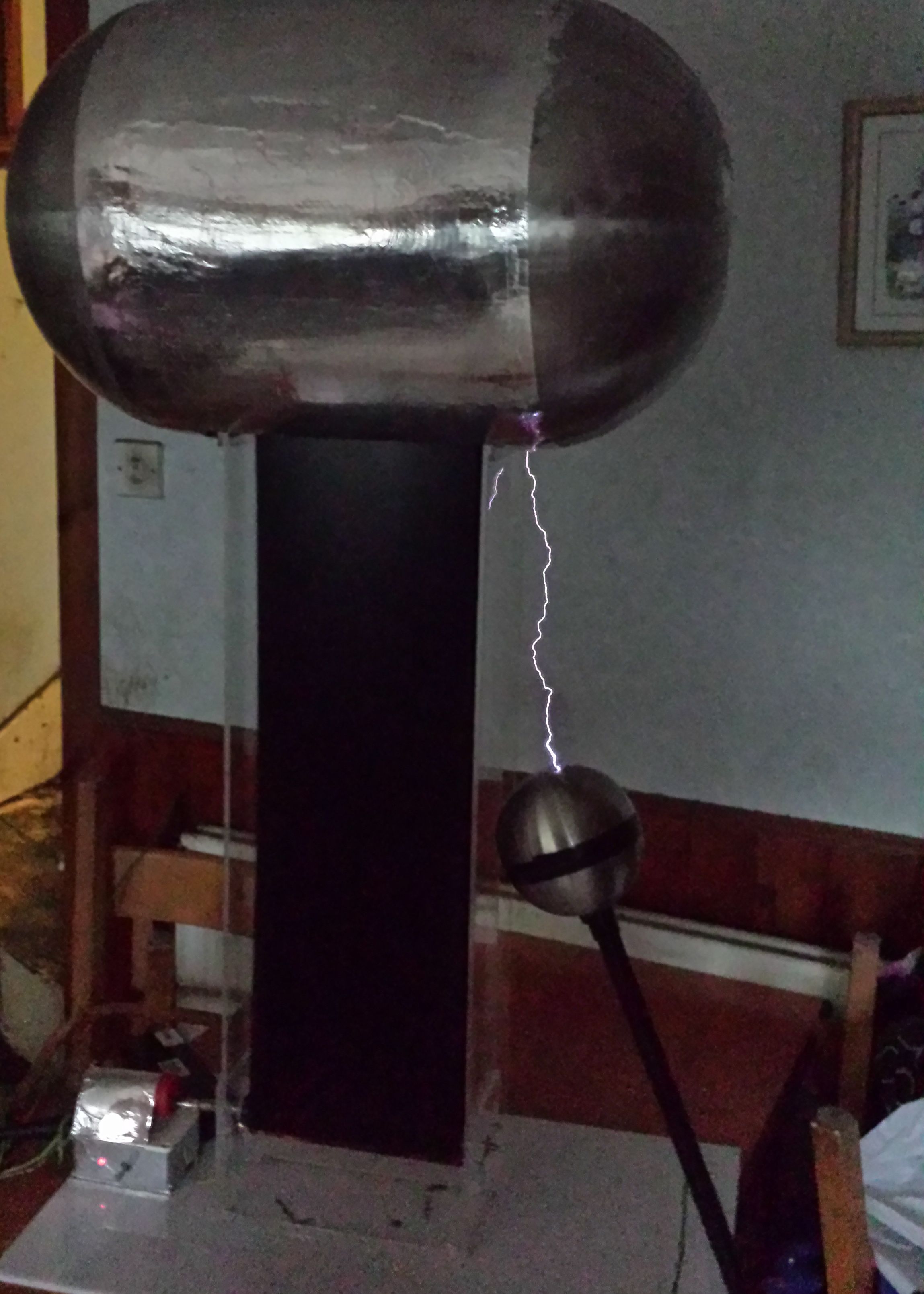
I’m my mind I can’t think of any situation where static electricity exists. Capacitors, Van de graph terminals (also capacitors) all store charge. But non are static, there is always leakage current. To charge these devices there must be current.

So is its not static electricity, its stored electricity (charge) or conventional electricity(current) ,  both or just electricity.

Reading Physics books there appears to be a whole set of laws that govern each “type” of electricity, but in reality the effects are always there. One of the problems is that ‘static’ electricity is generally taught with high DC voltages, current electricity is taught with low DC voltages. The effects you see are dominated by the voltage, for example.

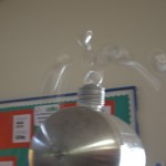
Electrical attraction occurs in all capacitors. But at high voltage the effects are much larger and so easier to see.
Resistive heating has a larger effect at low voltages, but is harder to see at high voltages (which is why transmission lines are high voltages)

The more you work on high voltage, or with high frequency electricity the more these effects become apparent.

So banish ‘static’ as a description and replace with high or low voltage, charge or current this is really what is going on.

Bill Beaty’s Thoughts on this What’s the Difference Between ‘Static’ Electricity and ‘Current’ Electricity?

1MV Van De Graff project – Notts Gaussfest

After a lot of work, I just managed to get everything to Notts Gaussfest. This was really the first time all of the pieces had run together for any length of time.

I found a number of issues. The belt stuck together at high charges, usually stopping the belt completely and the motor control would crash when there was a really good discharge.

The motor problem was a partially solved by coating the controller in aluminium foil, which at least let me run the VDG for the day at Notts Gaussfest.


1MV Van de Graff – First light

Details of the project

First light tonight 6″ sparks, not bad for the first time I’ve powered it up.

At the moment the limiting factors to the spark length/voltage is the unfinished top load and a problem with the belt. The top load has a very uneven surface, I believe I’m losing charge this way.

When the VDG starts charging the two sides of the belt are attracted to each other and they rub together, reducing the charging. I tried tightening the belt with no effect, so I have ordered 0.4mm (was 0.25mm) latex to make another thicker belt.

Work continues to complete the top load.

I2C control of LCD Display using YwRobot LCM1602 V2 & Raspberry PI

Using the YwRobot to control a 20×4 line display via I2C on a Raspberry PI, what could be easier.
PI display
Well, If all of the code was only for an arduino and there being no actual documentation or wiring diagram. Note: Example code IS NOT documentation.

Hey Ho, After some playing around I found the pin arrangement


addr, en,rw,rs,d4,d5,d6,d7,bl
0x27, 2, 1, 0, 4, 5, 6, 7, 3

0x27 is the i2c port address (bus 1 on newer PI’s)

I found this code snippet for a different set of boards http://www.rpiblog.com/2012/07/interfacing-16×2-lcd-with-raspberry-pi.html which was near, but made the display backlight flash and no text output.

So the hacking started…

Basically all of the control lines were on different pins, and I needed to control the backlight (via a wrapper on the i2c write code)

pylcdlib.py
import smbus
from time import *

#
# Modified from http://www.rpiblog.com/2012/07/interfacing-16×2-lcd-with-raspberry-pi.html to run
# 20×4 line display with YwRobot LCM1602 IIC V1 backpack
#

# General i2c device class so that other devices can be added easily
class i2c_device:
def __init__(self, addr, port):
self.addr = addr
self.bus = smbus.SMBus(port)

def write(self, byte):
self.bus.write_byte(self.addr, byte)

def read(self):
return self.bus.read_byte(self.addr)

def read_nbytes_data(self, data, n): # For sequential reads > 1 byte
return self.bus.read_i2c_block_data(self.addr, data, n)

class lcd:
#initializes objects and lcd
”’
Port definitions
addr, en,rw,rs,d4,d5,d6,d7,bl
0x27, 2, 1, 0, 4, 5, 6, 7, 3

”’

def __init__(self, addr, port):
self.lcd_device = i2c_device(addr, port)

self.backlight=1; #default to backlight on

def lcd_init(self):
#set 4 bit mode
self.lcd_device_writebl(0x30) #write
self.lcd_strobe()
sleep(0.005)
self.lcd_strobe()
sleep(0.005)
self.lcd_strobe()
sleep(0.005)
self.lcd_device_writebl(0x20)
self.lcd_strobe()

self.lcd_write(0x28)
self.lcd_write(0x08)
self.lcd_write(0x01)
self.lcd_write(0x06)
self.lcd_write(0x0C)
self.lcd_write(0x0F)

#wrapper to self.lcd_device.write fir backlight control
def lcd_device_writebl(self,value):
if self.backlight:
self.lcd_device.write(value | 0x08);
else:
self.lcd_device.write(value)

# control backlight on=1 or off=0
def lcd_backlight(self,on):
self.backlight=on
self.lcd_strobe()

# clocks EN to latch command
def lcd_strobe(self):
#bit 2
self.lcd_device_writebl((self.lcd_device.read() | 0x04))
self.lcd_device_writebl((self.lcd_device.read() & 0xFB))

# write a command to lcd
def lcd_write(self, cmd):
self.lcd_device_writebl((cmd >> 4)<<4)
self.lcd_strobe()
self.lcd_device_writebl((cmd & 0x0F)<<4) self.lcd_strobe() # self.lcd_device_writebl(0x0) # write a character to lcd (or character rom) def lcd_write_char(self, charvalue): self.lcd_device_writebl((0x01 | (charvalue >> 4)<<4))
self.lcd_strobe()
self.lcd_device_writebl((0x01 | (charvalue & 0x0F)<<4))
self.lcd_strobe()
self.lcd_device_writebl(0x0)

# put char function
def lcd_putc(self, char):
self.lcd_write_char(ord(char))

# put string function
def lcd_puts(self, stringin, line):
if line == 1:
self.lcd_write(0x80)
if line == 2:
self.lcd_write(0xC0)
if line == 3:
self.lcd_write(0x94)
if line == 4:
self.lcd_write(0xD4)

string=stringin + ” ” #blank out rest of line
string=string[0:20];#limit lines to 20 char

for char in string:
self.lcd_putc(char)

# clear lcd and set to home
def lcd_clear(self):
self.lcd_write(0x1)
self.lcd_write(0x2)

def lcd_cursoroff(self):
self.lcd_write(0x0c) #cursor and blink off

# add custom characters (0 – 7)
def lcd_load_custon_chars(self, fontdata):
self.lcd_device.bus.write(0x40);
for char in fontdata:
for line in char:
self.lcd_write_char(line)


Preventing (or at least reducing) SD corruption on Raspberry PI

From:
http://www.ideaheap.com/2013/07/stopping-sd-card-corruption-on-a-raspberry-pi/

Read for more info

The biggest offender for Filesystem writes on any linux system is logging. If you are like me, you don’t really look at /var/log after a recycle anyways. This area, and /var/run, a location where lock files, pid files and other “stuff” shows up, are the most common areas for mess-ups. Take a look at your blinking FS light on the board. Our goal is to make that light stay off as long as possible.

Set up tmpfs mounts for worst offenders.

The following two lines should be added to /etc/fstab:

none        /var/run        tmpfs   size=1M,noatime         00
none        /var/log        tmpfs   size=1M,noatime         00

There’s more, however. By default, linux also records when a file was last accessed.
That means that every time you read a file, the SD card is written to. That is no good! Luckily, you can specify the “noatime” option to disable this filesystem feature. I use this flag generously.

Also, for good measure, i set /boot to read-only. There’s really no need to regularly update this, and you can come back here and change it to “defaults” and reboot when you need to do something.

After this, /etc/fstab should look as follows:

proc            /proc               proc    defaults                    0   0
/dev/mmcblk0p1  /boot               vfat    ro,noatime                  0   2
/dev/mmcblk0p2  /                   ext4    defaults,noatime            0   1
none        /var/run        tmpfs   size=1M,noatime             0   0
none        /var/log        tmpfs   size=1M,noatime             0   0

Go ahead and reboot now to see things come up. Check the Filesystem light on your raspberry pi after it’s fully booted. You should see no blinking at all.

Disable swapping

One protection against SD card corruption is an optional, but potentially “I’m glad i did that” change to disable swapping.

The raspberry pi uses dphys-swapfile to control swapping. It dynamically creates a swap partition based on the available RAM. This tool needs to be used to turn off swap, and then needs to be removed from startup.

Run the following commands to disable swapping forever on your system:

sudo dphys-swapfile swapoff
sudo dphys-swapfile uninstall
sudo update-rc.d dphys-swapfile remove

After doing this, call free -m in order to see your memory usage:

pi@raspberrypi ~ $ free -m
             total       used       free     shared    buffers     cached
Mem:           438         59        378          0          9         27
-/+ buffers/cache:         22        416
Swap:            0          0          0

If you reboot, and run a free -m again, you should still see swap at 0. Now we don’t have to worry about tmpfs filesystems swapping out to hard disk!

From:
http://www.ideaheap.com/2013/07/stopping-sd-card-corruption-on-a-raspberry-pi/

Read for more info