Every year I make a badge for the Nottingham Gaussfest
Previous years I have just done a simple laser cut badge with a battery powered flashing LED, but this year I thought I’d do something a bit different.
My first idea was pushing the boat out a little too far, and after receiving the PCB’s I realised it would never work ( I don’t want to say what it was, as I have ideas for sort it in coming years)

So, as I was losing time quickly, I decided that I’d build a simple lightning detector. At the Gaussfest there are many, many machines that make sparks. So the idea was, when the exhibitors are making sparks, their badge lights up, what could be easier.
If I was going to do this, the badges MUST be there and working on the day. No point in having a lightning detector badge on a non-teslacoiling day.
I roughed up a circuit, based on Extreme kits lightning detector. To keep the LED on for a few seconds I used an NE555 timer.
The circuit was tested on bread-board and if I used a CMOS NE555 would run really well with a 3V supply. (Non CMOS 555’s need 6v AND take a lot more current)
I wanted to use through-hole as Extreme Kits’s lightning detector circuit used almost all of the same components but, I didn’t want ugly through hole wires on the front of the PCB, so I opted for through hole components, but surface mounted.

Happy with the circuit, I edited the PCB layout so I could get two boards in a 10x10CM order, which is the most cost efficient way of getting these PCB’s made with my supplier.
I also ordered 50 NE555 (CMOS) as the best prices came from china the PCB’s and the chips should arrive at roughly the same time.
After a couple of weeks the PCB’s and chips arrived and I quickly built one up and put in a CR2032 3v battery
It didn’t work, nothing…
Nothing I did would make it work, but everything seamed fine. Eventually I put it onto my PSU and tried it at 3V from there.
Nothing.
Scoping the output, it worked, but wouldn’t drive the LEDS, I tried every variation of LEDS I had, nothing worked (apart from a VERY dull glow).
On a hunch, I tried the circuit at 6V
Everything worked fine. Eh ???
I then occurred to me that my CMOS NE555’s (from China) may not be CMOS, I swapped one for a lone known good chip I had, the circuit worked fine. (insert swearwords here)
With not enough time to reorder CMOS 555’s, I needed a solution.

Well, CR2032’s are 3v and 3.2mm thick, CR2016’s are 3v and 16mm thick, I could fit two 2016’s in a 2032 socket giving me 6V. This worked, but the bottom battery would short. A small piece of tape sorted that quickly. The only down side now is that 2×2016’s have half the current capacity of 1×2032 and the non CMOS 555 chips are a lot more greedy. In a trial, the badges lasted 14 hours. I only needed them to last 8. I was hoping for a few days where I could put in the batteries and pack the badges. Adding a pull away tab which could turn them on, on the morning of the event sorted that. Finally I had a solution.

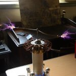
So, I built a batch of the PCB’s
Half of them worked, the other half refused to do anything. (insert other swearwords here)
On closer inspection the second PCB on each panel wouldn’t work.
Referring back to the PCB design I spotted my error, The fills would against ground, as I’d copied the PCB the signals for GND were no longer GND so the fills avoided the pads. All the GND connections were not connected. I didn’t have time to reorder the PCB’s
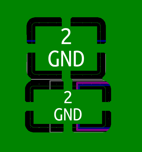

Luckily, my PCB house had done a couple of extra PCB’s, so I had JUST enough. The two organiser badges though, had a pretty addition of gold wires on the back joining all the GNDS together.

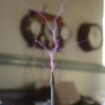
Finally a box of working badges, with only a few days to go. The only problem was I ran out of time, and I never got to test the badges with a real tesla coil or Wimshurst.

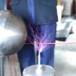
Luckily on the day they performed pretty well, If I was going to be harsh, they triggered occasionally on static discharges with peoples clothes, and their range was poor when they were close to the chest, but 1-2M away from my and other tesla coils they lit up wonderfully.
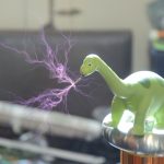
A badge being triggered by a discharge from my Shake sphere (that’s the background noise)
So my tips for designing a badge for an event.
What is a Gaussfest ?
Nottingham Gaussfest is a yearly meeting of a loose group of friends sharing a common interest in high voltage equipment and Tesla coils.In the USA these meetings are always referred to as Teslathons, a reference to Nicola Tesla who’s tesla coils always feature prominently at these events. We decided, being European, we would adopt Carl Friedrich Gauss as the scientist, due to all the devices also required a high magnetic field and we wanted to differentiate ourselves. Hence the term Gaussfest.

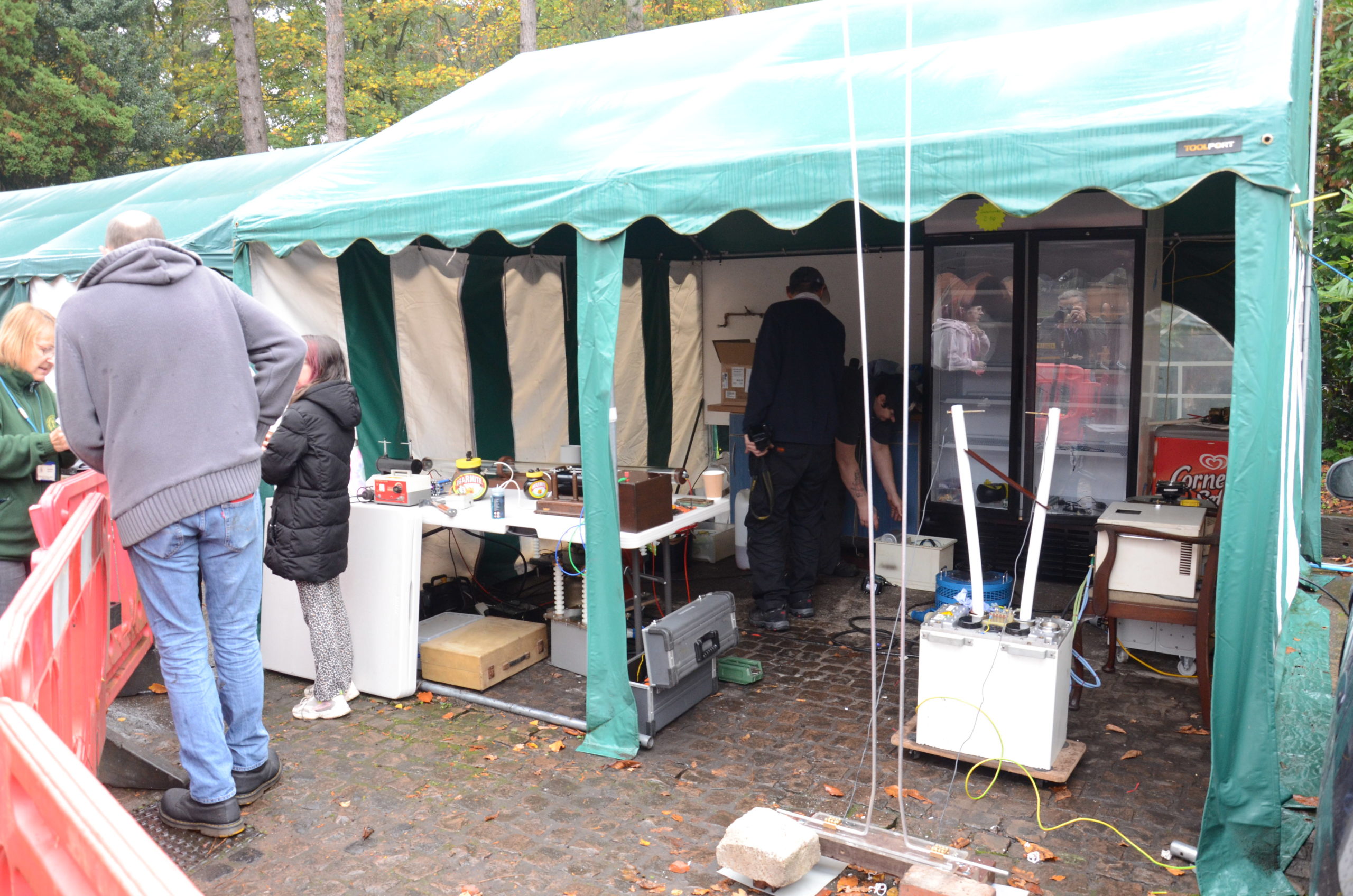
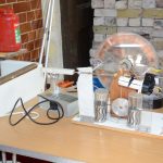
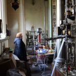
The equipment that appears at the Gaussfest is entirely dependent on the Exhibitors present, and their current interests. Usually there will be a collection of various types of Tesla coils, and a collection of static electricity generators like Van-De Graff machines and Wimshurst machines. But each year someone surprises me with something different, or new.
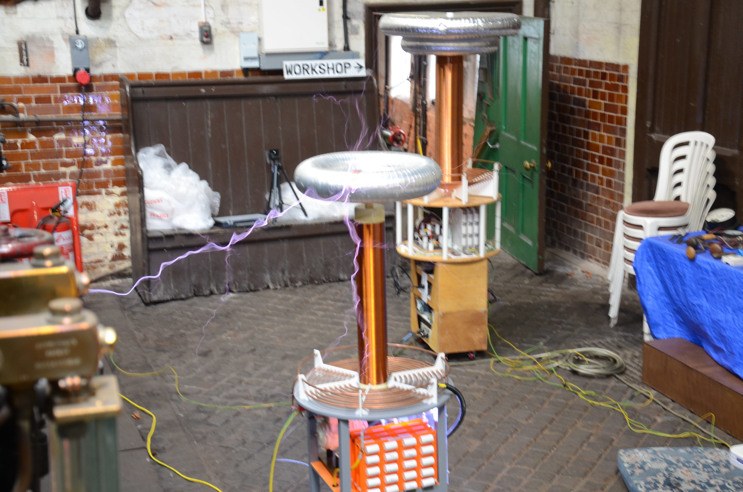
Tesla coils are the most common high voltage device we get, are essentially a large transformer. Near the bottom of the tesla coil is a radio frequency generator either electronic or mechanical, driving a primary winding with a small number of turns. The Secondary coil (the tall one) has a much larger number of turns of around 800-2000 turns typically. And at the top if this, a topload where the high voltage comes out. We get tesla coils of all sizes from a 50mm high, to over 2M tall at the Gaussfest.

The Static generating machines our exhibitors bring are even more are varied. The common ones are a Van de Graaff machine, uses a belt to transfer charge up to the top dome where it is stored, and the Wimshurst machine uses a pair of contra-rotating disks to multiply charge and store it into a pair of capacitors. Again the sizes of these machines vary from 200mm tall to 1.5MAlthough the electrical discharges from these machines look dangerous, they are entirely safe if viewed from a distance, and our exhibitors are very experienced with the operation of their machines.

Or Exhibitors are happy to talk about how their machines work and the problems with their construction, although if they are preparing them for a demonstration, or have problems please give them “thinking room” as their safety, and the safety of their equipment is paramount. All our exhibitors are all amateurs and make and demonstrate high voltage equipment for fun. The Gaussfest is their opportunity to display what they have been working on.

Commercial high voltage engineering is expensive, due to this many of the exhibits on display will have been made totally or partially from household items, surplus, and any available electronic equipment, often with items multiplied up to deal with the high voltages/currents that are required. To keep the cost down, the equipment is usually run at the very maximum of its tolerances. These devices are rarely engineered for their longevity, so failures are quite common, and this trade-off is very much part of the hobby. Due to this, we do not have planned schedules for the demonstrations, as equipment WILL FAIL (and be repaired) during the day, although we will endeavour to have something always happening.
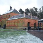
When the Gaussfest moved to Papplewick in 2017, we were very conscious that for us to do our activities, Papplewick pumping station must get something back, So Papplewick allow us to meet, and we let the public see what we do and give demonstrations to give back to the Pumping station. As much of what we do can be dangerous, this trade-off is some restrictions in access to the station to ensure your safety.
The ini file sets the defaults for the Rc2040 and substitutes for switches and buttons on boards that have none.
It allows you to select the ROM, RAM settings, and CPM settings for the emulation.
Requires CPM Inc Transient Apps SIO2.img,CPMIDE.id, 24886009.BIN and rc2040.ini for SIO2 as below
ROM has basic at address 0x0000 (000) ROMsize 0x2000
ROM has basic at address 0x2000 (001) ROMsize 0x2000
CP/M / Basic via monitor at address 0x4000 (010) ROMsize 0x4000
Small Computer Monitor at 0xe000 (111) ROMsize 0x2000
More detail at [https://github.com/RC2014Z80/RC2014/tree/master/ROMs/Factory]
Config with no switches and other emulation settings for SIO2
[IDE]
idefile = “CPM Inc Transient Apps ACIA.img”;
idefilei = “CPMIDE.id”;
[ROM]
a13 = 0; // Address switches 0=0x0000 100=0x8000 111=0xE000
a14 = 1;
a15 = 0; // ROM file as ROM source
romfile = “24886009.BIN”; // source for Rom Loading – see a13 a14 a15
romsize=0x4000; // Size of ROM
[CONSOLE]
port = 1; // Console port 0=UART or 1=USB
[EMULATION] // ACIA=0 SIO=1;
serialtype = 1; //SIO selected
inidesc=”SIO using 24886009.BIN”; //describe the ini
[SPEED] //vPico overclocking *1000 Mhz
overclock = 250; //overclock the PICO at 250 x 1000
Config with no switches and other emulation settings for ACIA
Requires CPM Inc Transient Apps ACIA.img,CPMIDE.id, R0001009.BIN and rc2040.ini as below
Rom has basic at address 0x0000 (000)
CP/M via monitor at address 0x8000 (100)
Small Computer Monitor at 0xe000 (111)
More detail at [https://github.com/RC2014Z80/RC2014/tree/master/ROMs/Factory]
Config with no switches and other emulation settings
[IDE] idefile = “CPM Inc Transient Apps ACIA.img”;
idefilei = “CPMIDE.id”;
[ROM]
a13 = 0; // Address switches 0=0x0000 100=0x8000 111=0xE000
a14 = 0;
a15 = 1;
// Size of ROM
romsize=0x4000;
#ROM file as ROM source romfile = “R0001009.BIN”; // source for Rom Loading – see a13 a14 a15
[CONSOLE] // Console port 0=UART or 1=USB
port = 1;
[EMULATION]
serialtype = 0; // ACIA=0 SIO=1; ACIA selected
inidesc=”ACIA using R0001009.BIN”; //describe the ini
[SPEED] //Pico overclocking *1000 Mhz
overclock = 250; //overclock the PICO at 250 x 1000
[ROM]
jumpto = 0x2000; // non standard start vector (e.g not 0x0000);
ramonly = 1;// ram only (no rom, 64K load from romfile);
[PORT]
pioa=0; // set the IO address of the 8 bit port
[IDE]
ide=0; //Turn off IDE
iscf=1; //enable cf file as idefile, rather than the .img format
[EMULATION]
inidesc=”Broken INI file”; //ini file description to show at boot
[DEBUG]
trace = 0 // trace details in RC2040.c
You can edit the contents of the SD card .img file using CPM Manger and directly add or remove files in the CPM img.
CPM Manager is available here.
If you are using Linux (or windows), you can use the CPM tools to add or remove files. CPM tools are available here If you are using CPM tools, you will need a diskdef files. Disk defs for the RC2040 format(s) are available here DiskDefs
8 bits of a simple IO post are brought out to the RP2040 GPIO as an input/output port. The port is configured on the fly, So if you execute an IN instruction, the port becomes an input port, (with pull ups). If you execute an OUT instruction the port becomes an output port. (The Original RC2014 port is arranged as 8 outputs and 8 inputs, but there were only 8 bits available. )
Details are in the Circuit diagram . Switches and buttons are not required. But give you direct access to the ROM addresses (top 3 address lines) and the buttons allow for a z80 reset, Dump and other functions.
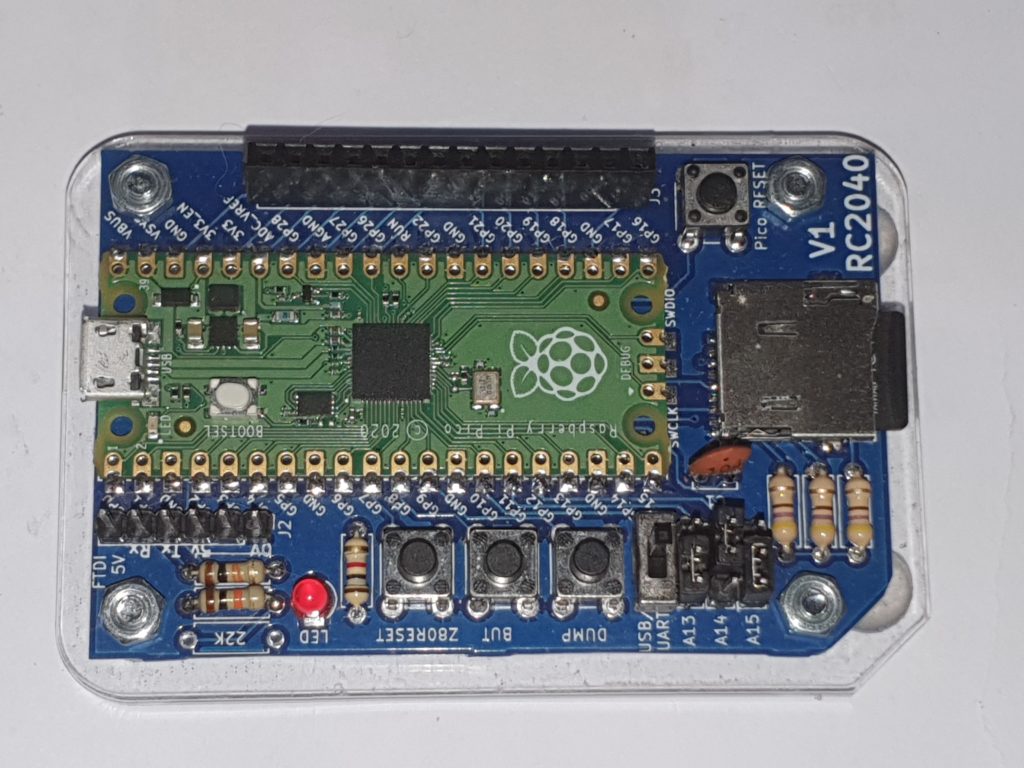
A complete kit of parts for the RC2040 is available here from Extreme Kits
A friend of mine was asking me about MSF time reception and I realised I only knew some of the basics. So this sent me on a hunt for more information.
In the UK the MSF tme signal is sent on a carrier of 60khz from a transmitter in Anthorn Yorkshire with a radiated power if 17KW http://www.npl.co.uk/science-technology/time-frequency/products-and-services/time/msf-radio-time-signal
17KW sounds large, but this is at 60 Khz, the efficiency of ariels less than 2.5Km (a half a wavelength of 60Khz) long with all round coverage is going to be much less than 1, probably a lot less than 1. The old Time Signal transmitter at Rugby was in the order of 200KW. I can only assume the new transmitter is of a similar power to get a ERP of 17Kw.
After a little looking around, I discovered the web site of Andy (http://www.burningimage.net/msfsimulator) who has made a MSF transmitter for 60Khz using a Pc’s sound card using the third harmonic of 20Khz to produce a 60 Khz signal and written the Python code to encode a date time into the MSF protocol.
So with most of the heavy lifting done, I started to think about what I had to hand. Raspberry Pi’s…
My first thought was using the frequency generator built in to the PI to give the 60Khz as used in many PI transmitter projects , but there were limitations in trying to get 60Khz. So the next thought was a PWM output. A bit of googling gave me the formulae for the frequency of the hardware PWM on a PI
pwmClockDivisor=19200000/PWMRange/Freq
PWMrange is the number of “levels” you can specify for the PWM signal.
After some experimenting I found that you could set the range really small e.g. 2 Which is great if you sent the PWM a 0 it goes off. If you send it a 1 you get 50/50 Mark Space, ideal. Setting the pwmClockDivisor to 160 gives a 60Khz output.
The Wiring PI Wrapper for Python supports this setup. So setting the hardware PWM is a case of
io = wiringpi.GPIO(wiringpi.GPIO.WPI_MODE_PINS)
io.pinMode(PIN,io.PWM_OUTPUT)
io.pwmSetClock(160)
io.pwmSetRange(2)
The wiring Pi for Python setup is detailed here http://raspi.tv/how-to-install-wiringpi2-for-python-on-the-raspberry-pi
[code lang=”py”]
#——————————————————————-
# This script uses PWM on GPIO PIN 18 to transmit an MSF timecode
#
# Save it as msf.py somewhere on your Pi.
#
# Run it with ‘python msf.py’
#
# Requires the Wiring Pi Python Library
#
# Based on Audio MSF code from
#
# http://www.burningimage.net/msfsimulator
# by
# andy@burningimage.net
#
# PWM output, Frequency and DateTime Code Added by Derek Woodroffe
# tesla@extremeelectronics.co.uk
#——————————————————————-
#——————————————————————-
# Set the time/date to transmit below.
#
# The date time startes at the datetime you set regardless of local
# clock settings
#
# Use groundhogday=True to repeat the same "day" every 24 hours.
#
# Your clock(s) should have set its time by around minute 5.
# Some clocks only look at MSF data every 12 hours.
#
# The day of the week is automatically set to the correct value
#——————————————————————-
import time
import math
import wiringpi
import datetime
#—————– Carrier Frequency ——————————
#UK tested, others un-tested not sure about the modulation
Freq=60000 #60Khz UK/Japan – 66.66Khz Russia – 77.5Khz Germany/Taiwan
#———————– Set inital time —————————
#start with a defined datetime
mmfdt = datetime.datetime(2019,4,1 ,6,1) #datetime year,month,day,hour,min
#Run with current time
#mmfdt = datetime.datetime.now()
#run 1 hour in the future
#mmfdt = datetime.datetime.now()+datetime.timedelta(0,0,0,0,0,1,0) #timedelta([days[, seconds[, microseconds[, milliseconds[, minutes[, hours[, weeks]]]]]])
#———————— Groundhogday —————————–
#repeat after 24 hours.
#groundhogday=True
#dont repeat
groundhogday=False
#———————— Parity ———————————–
# Set to 1 to transmit proper parity bits
enableparity = 1
#——————————————————————-
def carrier_on(length):
io.pwmWrite(PIN,1)
time.sleep(0.001*length)
def carrier_off(length):
io.pwmWrite(PIN,0)
time.sleep(0.001*length)
def minutemarker():
carrier_off(500)
carrier_on(500)
def send01():
carrier_off(100)
carrier_on(100)
carrier_off(100)
carrier_on(700)
def send11():
carrier_off(300)
carrier_on(700)
def send00():
carrier_off(100)
carrier_on(900)
def send10():
carrier_off(200)
carrier_on(800)
bcdlist= [80, 40, 20, 10, 8, 4, 2, 1]
#setup PWM GPIO pin 18 (pin1) Hardware PWM at Freq
PIN=1
#pwmClock divisor=19.2e6/2/Frequency
pwmClock=19200000/2/Freq
io = wiringpi.GPIO(wiringpi.GPIO.WPI_MODE_PINS)
io.pinMode(PIN,io.PWM_OUTPUT)
io.pwmSetClock(pwmClock)
io.pwmSetRange(2)
io.pwmWrite(PIN,0)
mmfdts=mmfdt
while(True):
year = mmfdt.year
month = mmfdt.month
dayofmonth = mmfdt.day
dayofweek = (mmfdt.weekday()+1) % 7 #0 = sunday, 1 = monday etc.
hour = mmfdt.hour
minute= mmfdt.minute
# Ignore the ‘0’ element in the list as it confuses matters
# with the timecode
timecodeA = [0] * 60
timecodeB = [0] * 60
# Convert the year to BCD and store in the correct place in the timecode
bcdindex=0
temp = year
sum=0
for i in range(17,25):
if temp >= bcdlist[bcdindex]:
timecodeA[i] = 1
sum += 1;
temp -= bcdlist[bcdindex]
bcdindex += 1
# Work out the parity bit for 17-24
if (sum % 2) != 1:
timecodeB[54] = enableparity
# Now do the month
bcdindex=3 #starts at 10
temp = month
sum = 0
for i in range(25,30):
if temp >= bcdlist[bcdindex]:
timecodeA[i] = 1
temp -= bcdlist[bcdindex]
sum += 1
bcdindex += 1
# Do the day of month
bcdindex=2 #starts at 20
temp = dayofmonth
for i in range(30,36):
if temp >= bcdlist[bcdindex]:
timecodeA[i] = 1
temp -= bcdlist[bcdindex]
sum += 1
bcdindex += 1
# Work out the parity bit for 25-35
if (sum % 2) != 1:
timecodeB[55] = enableparity
# Do the day of week
bcdindex=5 #starts at 4
temp = dayofweek
sum = 0
for i in range(36,39):
if temp >= bcdlist[bcdindex]:
timecodeA[i] = 1
temp -= bcdlist[bcdindex]
sum += 1
bcdindex += 1
# Work out the parity bit for 36-38
if (sum % 2) != 1:
timecodeB[56] = enableparity
# Do the hour
bcdindex=2 #starts at 20
temp = hour
sum = 0
for i in range(39,45):
if temp >= bcdlist[bcdindex]:
timecodeA[i] = 1
temp -= bcdlist[bcdindex]
sum += 1
bcdindex += 1
# Do the minute
bcdindex=1 #starts at 40
temp = minute
for i in range(45,52):
if temp >= bcdlist[bcdindex]:
timecodeA[i] = 1
temp -= bcdlist[bcdindex]
sum += 1
bcdindex += 1
# Work out the parity bit for 36-38
if (sum % 2) != 1:
timecodeB[57] = enableparity
#Bits 53A – 58A should always be 1
for i in range(53,59):
timecodeA[i] = 1
print(str(year).zfill(2) + "-" + str(month).zfill(2) + "-" + str(dayofmonth).zfill(2) + " " + str(hour).zfill(2) + ":" + str(minute).zfill(2)+ " – " + str(dayofweek) )
#print("A bits: " + str(timecodeA[1:]))
#print("B bits: " + str(timecodeB[1:]))
# Now play the timecode out
minutemarker()
for i in range(1,60):
if (timecodeA[i] == 1) and (timecodeB[i] == 1):
send11()
elif (timecodeA[i] == 0) and (timecodeB[i] == 1):
send01()
elif (timecodeA[i] == 0) and (timecodeB[i] == 0):
send00()
elif (timecodeA[i] == 1) and (timecodeB[i] == 0):
send10()
mmfdt = mmfdt + datetime.timedelta(0,60) #timedelta([days[, seconds[, microseconds[, milliseconds[, minutes[, hours[, weeks]]]]]]])
if (groundhogday):
if (mmfdt-mmfdts>datetime.timedelta(1)):
#restart day
mmfdt=mmfdts
print ("RESTART DAY")
[/code]
Then
io.pwmWrite(PIN,1) turns on the 60 Khz and io.pwmWrite(PIN,0) turns it off.
I replaced all of Andy’s Sound Card Code with functions that mimicked the operation, but used the PWM commands above and a sleep to give me the correct on/off times (yes, sleep is inaccurate, this could be improved)
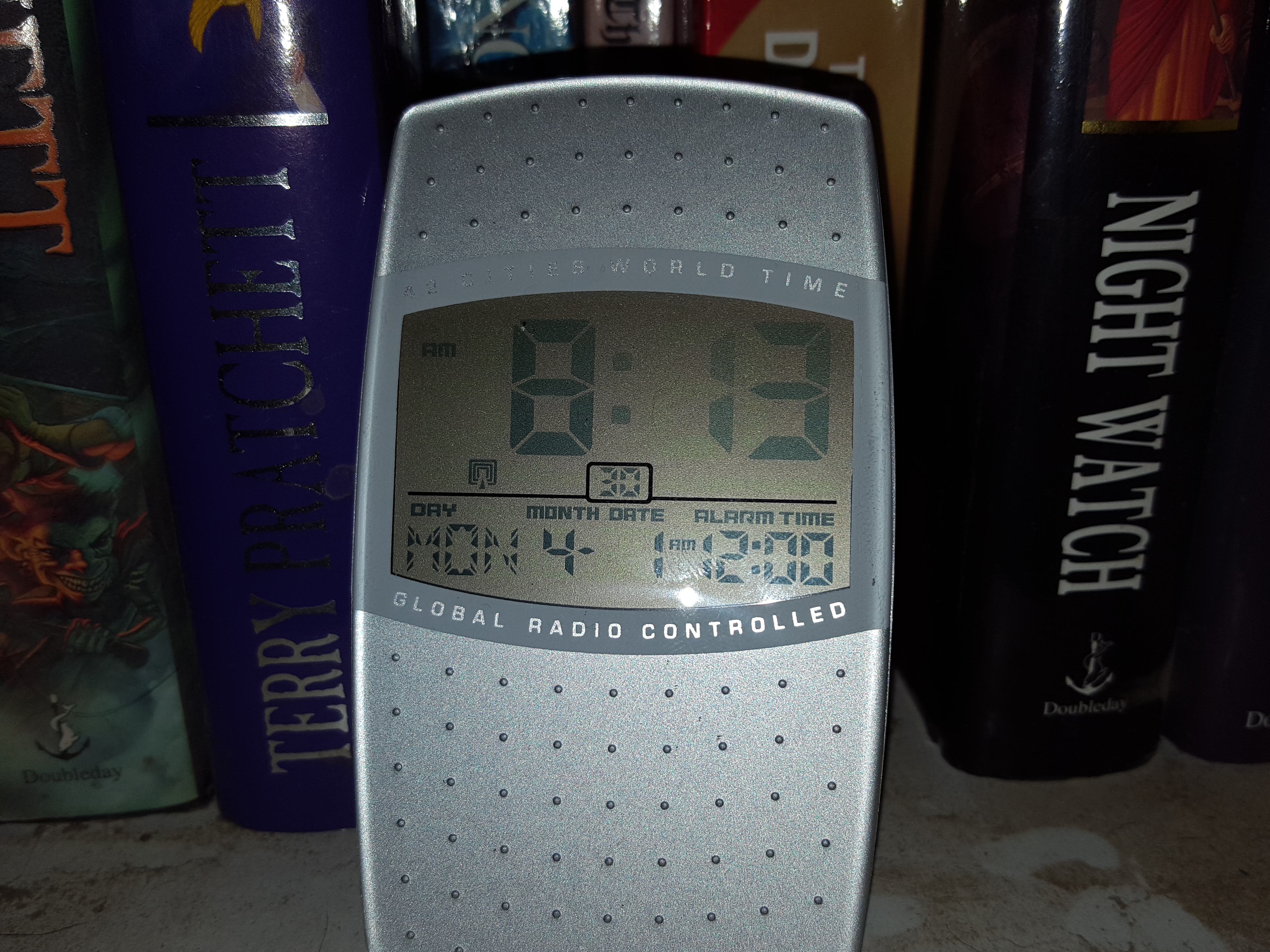
Adding a short wire to GPIO 1 (PIN18) and placing this near an MSF clock, worked… (it was 4 in the afternoon, and not April 1st 2019)
But if you want some fun, this close is probably not enough 🙂
Note: Transmitting on this frequency is Illegal and It is possible to affect all sorts of equipment that uses MSF. The transmitter below has a range of only a few feet and so is unlikely to cause any unexpected effects, but don’t do this where there is any medical or industrial control equipment that may use the time signal.
Oh, and your neighbour may get quite miffed if his alarm clock goes off at the wrong time…
So adding some power..
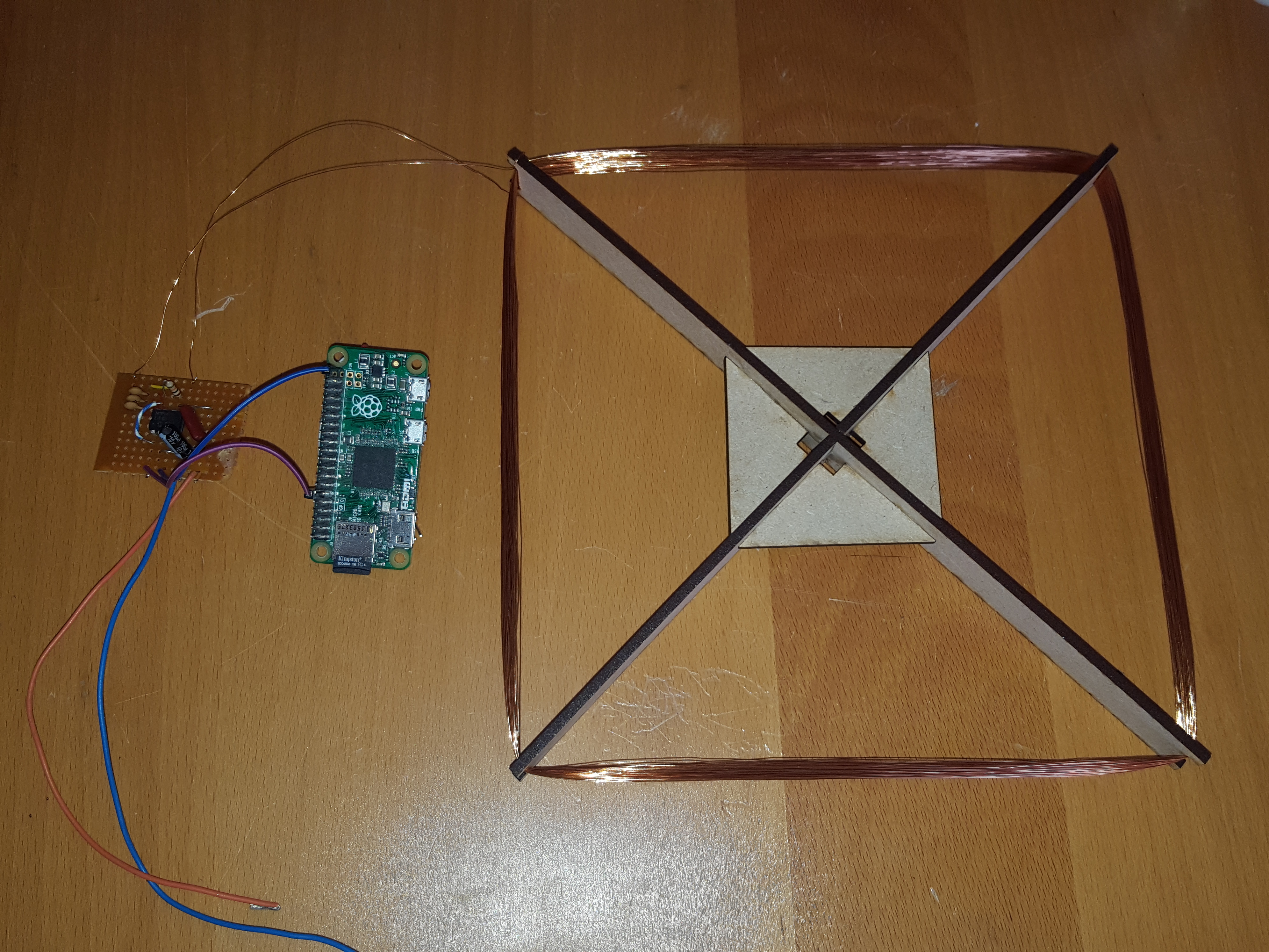
I made an X of 300mm strips of MDF and wound 100Turns of 0.3mm enamelled wire around the structure.
This I drove from a MC4428 mosfet driver. Using both channels together gives a full bridge drive of up to 1.5A and can run up to 24V.
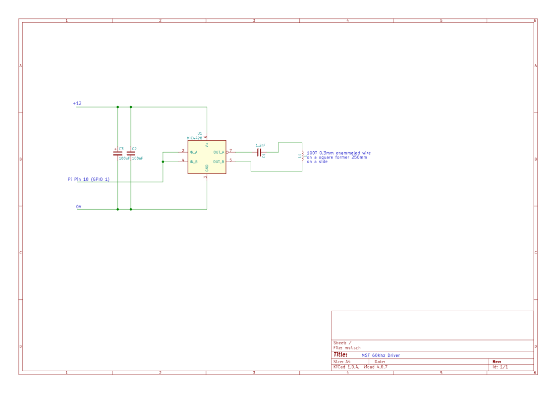
C1 will need to be modified to get your coil in tune. Tuning can easily be done by monitoring the Cap to coil connection and varying the value of C1 for maximum voltage. Beware that the voltage on C1 can get to about 100V when in tune, so keep it away from your PI#s GPIO
(And other things too)
The Circuit generates about 1W of power, but remember the ariel is only a fraction of the 2.5Km dipole required for 1:1 ERP , so the actual ERP is much lower. Mine will “correct” clocks time at a range of about 4-5 Meters.
Key in the dark has been played in Scout groups and youth groups for as long as I can remember.
The idea of the game is one Scout is blindfolded and sat on a chair with a large set of keys underneath. He is “armed” with a torch. Usually a number of obstacles and places to hide are set up around them. The rest of the scouts need to stealthily get to the keys without the Scout shining the torch on them. If they are hit by a touch beam they are defined dead and have to either sit out the game, or start from the beginning again. The idea is that any sound made by the scouts in their approach means a torch shone their way.
Of course in practice a torch is not the ideal “weapon” although rules are that the torch is only to be used intermittently, it is basically an infinite resource and is usually shone around with abandon. Plus the operator being blindfold, they have no idea if the touch is on or off. The other main problem is that the torch beam diverges so much that multiple asalients can be cought at once.
So I started to  look at alternatives. As 5W leds are cheap I thought of one of these as a source, combined with a 10 x 70mm focal length lens from a watchmakers eyeglass (loupe) in a 20mm tube. I could get a pretty narrow, bright beam.
Mounting the LED on a piece of copper allowed for any heat from the led to escape. 
Of course, I needed a way of switching this, so I used a MC4427 1.5A mosfet driver, purely as it was a single chip solution and mainly as I had one to hand.
I dead bug soldered it, as there were only 4 connections. and glued the driver to the back of the heatsink.
 I had had the idea of “charge” to keep down the number of flashes, the idea being that every press of the button would freeze out the user for 0.5 Seconds. To show this, I thought of a number of neopixels along the barrel. So these were attached with some acrylic rings to spread the light out
Whilst I was thinking about the design of this, I was given an Adafruit Feather Huzzah
This was ideal, as it had a Lipo PSU and charger built in, and plenty of IO, coupled with a 25mmx9mm LIPO battery it gives loads of power..

Plus If you use MicroPython you got the neopixel support.
Realising that the operator would be blindfolded, I wanted some feedback so they would know when the torch was us ed. After trying a solenoid, I found this had two problems. 1. It was power hungry. 2. It took up a load of space. So I went back to a large’ish vibration motor (also to hand)

I had decided that the whole thing should fit in a tube no more than 40mm in diameter, so I laser cut some supports and hung the whole lot from two m3 threaded bars. After many attempts I finally got the acrylic into pieces that would support the electronics and battery and assembled the whole thing together. 
Of course, I’d forgotten the buttons. These needed to be at the front, but so the case could be removed they needed to connect at the back.
After a couple of attempts with internal wiring, that got cought up either putting it together or taking it apart. I eventually put the wires on the outside, covered the whole handle, wires and everything in leather and connected the buttons with a cable at the back.
The USB cable for power (and programming) currently exits out of the back, but is soon to be replaced with a micro socket. There is also a small switch for the units power.
The next addition was a burst fire mode, you get 5 shots in quick succession, but it takes longer to recharge.
I also added an auto power off, if left for 60 seconds.
Circuit Diagram [gview file=”http://www.extremeelectronics.co.uk/wp-content/uploads/2018/04/kitd.sch_.svg”]
Final Touches…

 End plate with USB charging port and On off switch.
Unfortunately as I take the power for the motor, Neopixels and the main LED straight from the battery Powering down is a two stage process. First you press and hold both buttons. After a few seconds everything is turned off. Then you can switch off the uP. I do it this way as I don’t have to switch everything on to charge it.
The finished Torch


Code
[code]
import machine, neopixel, time, utime
np1 = neopixel.NeoPixel(machine.Pin(12), 8)
np2 = neopixel.NeoPixel(machine.Pin(13), 8)
LED5w = machine.Pin(14, machine.Pin.OUT)
B1 = machine.Pin(5, machine.Pin.IN, machine.Pin.PULL_UP)
B2 = machine.Pin(2, machine.Pin.IN, machine.Pin.PULL_UP)
vib = machine.Pin(4, machine.Pin.OUT)
LED5w.off()
firec=(255,255,255)
chargec=(0,20,0)
black=(0,0,0)
OffTime=60
def fire(fx):
for x in range(0,fx,1):
for a in range(8):
np1[a]=firec
np2[a]=firec
np1.write()
np2.write()
time.sleep_ms(4)
np1[a]=black
np2[a]=black
np1.write()
np2.write()
LED5w.on()
vibrate()
time.sleep_ms(100)
LED5w.off()
def charge(cx):
for a in range(8):
np1[a]=chargec
np2[a]=chargec
np1.write()
np2.write()
time.sleep_ms(cx)
def vibrate():
vib.value(1)
time.sleep_ms(70)
vib.value(0)
charge(63)
start=utime.ticks_ms()
while(B1.value() or B2.value()):
if not B1.value():
fire(1)
start=utime.ticks_ms()
charge(63)
if(not B1.value()):
time.sleep_ms(1000)
if not B2.value():
fire(5)
start=utime.ticks_ms()
charge(350)
if(not B2.value()):
time.sleep_ms(3000)
if ((utime.ticks_ms()-start) > OffTime*1000):
for a in range(7,-1,-1):
np1[a]=black
np2[a]=black
np1.write()
np2.write()
time.sleep_ms(50)
np1[0]=(0,0,10)
np1.write()
while(B1.value()):
time.sleep_ms(200)
start=utime.ticks_ms()
charge(63)
vibrate()
for a in range(7,-1,-1):
np1[a]=black
np2[a]=black
np1.write()
np2.write()
LED5w.off()
[/code]
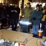
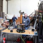
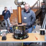
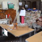
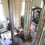
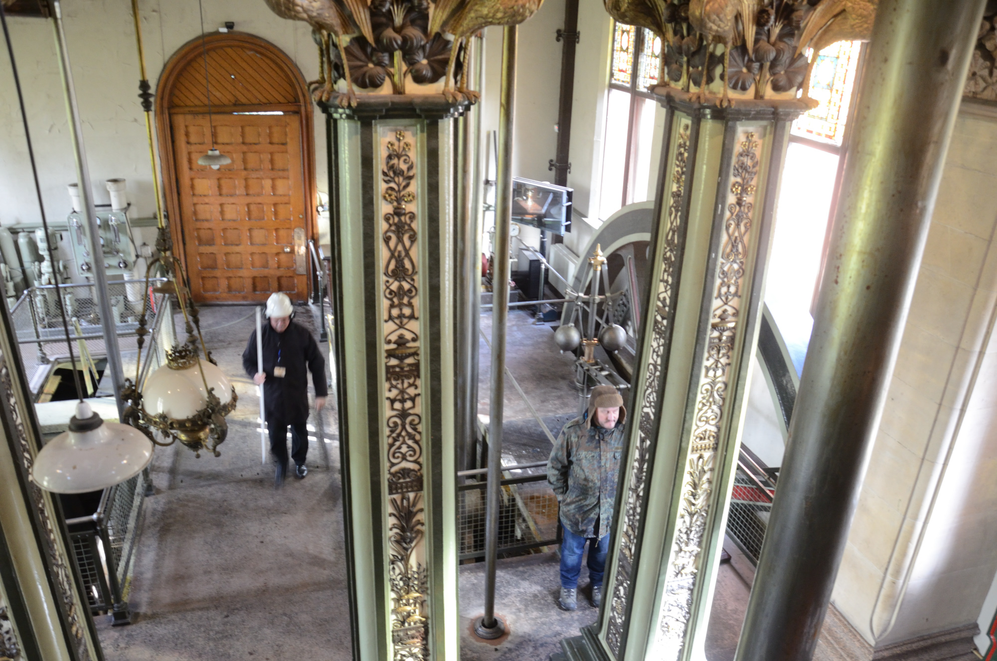
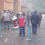
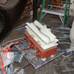
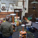
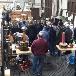
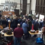
What a great day at Papplewick Pumping station. The change of venue caused some teething problems with space and I caused some problems with exhibitors names (no change there!) Over 140 visitors, three film crew’s on the day and 12 Exhibitors.
Danger, danger, high voltage! 🌩 pic.twitter.com/2FbIBQyc28
— BBC Radio Nottingham (@BBCNottingham) March 22, 2018
The pumping station were great in sorting out our rather strange needs and were over the moon about the attendance (they ran out of bacon in the cafe, apparently the indication of a good day). All proceeds from the day went directly to the Pumping station.
Photos from the day, If you, or your equipment is missing, please email me a picture/video. It was such a busy day I missed a lot of things.
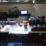
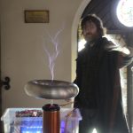
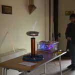
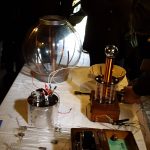
Derek’s (my) Equipment
Sam’s Equipment
Tony/Leicester Hackspace
Alex’s Equipment
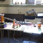
Dave’s Equipment
Jason’s Equipment
Roger’s Equipment
Chris’s Equipment
Chris’ Battery powered Tesla coil


Andrews Equipment
Earl
After a number of valiant attempts and a few disasters. Earl unfortunately failed to get his coil working. This was a great shame as the travel and effort he put in was huge. I would have loved to see his coil in action again. I especially wanted to see his bottle cap bank in action.


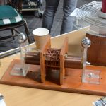
Robert’s Jacobs ladder

Groups
Papplewick Pumping station
A superb venue, although a bit cold, mitigated by a superb on site Cafe…


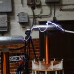
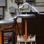
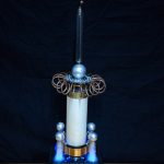
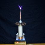
Flashing Light Prize 2017 second entry
So I had a better idea… and as far as I know there is no restrictions on entering twice.
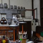
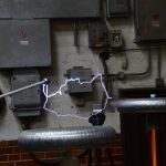
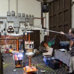
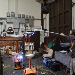
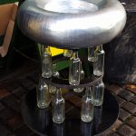
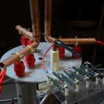
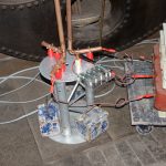
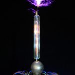
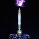
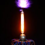
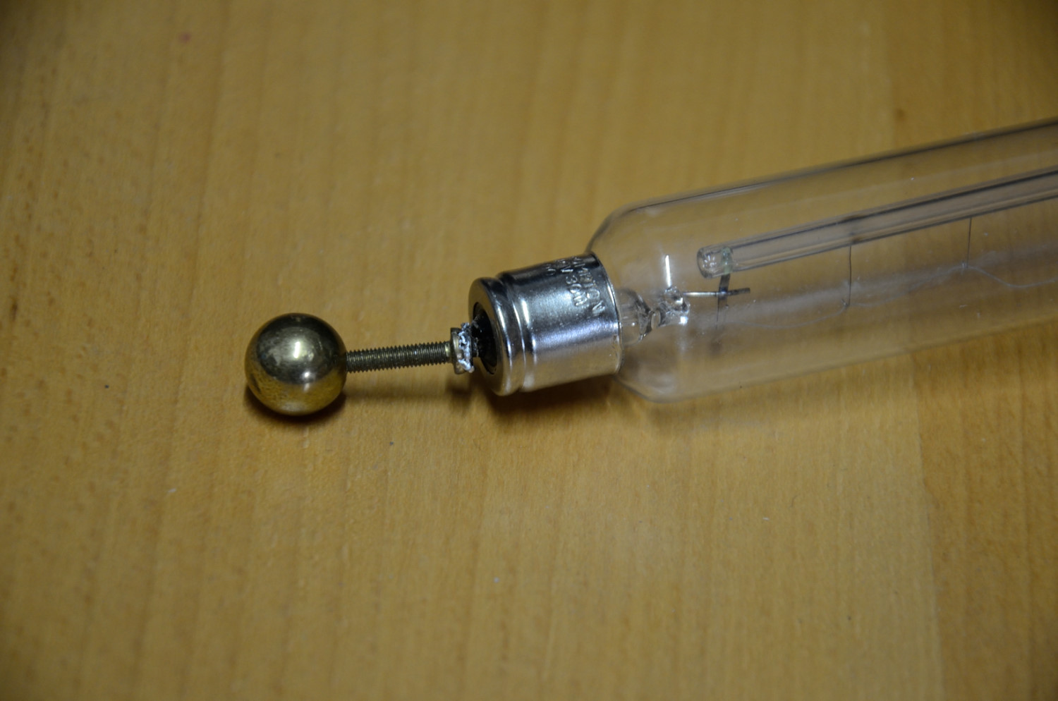
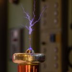
This time, I needed some thing more impressive. I’d been tinkering with a demonstration of lighting a bulb with a single connection for a while, so I tied it in with that. Unfortunately the only (working) tesla coil that I have that has enough power (actually RMS current at the topload) is the Aetheriser. So that is the coil I had to use.
A quick test with a long filament lamp proved the idea workable, but the free connection got a bit warm (e.g. too hot to touch) so I added a brass ball protection to the free end
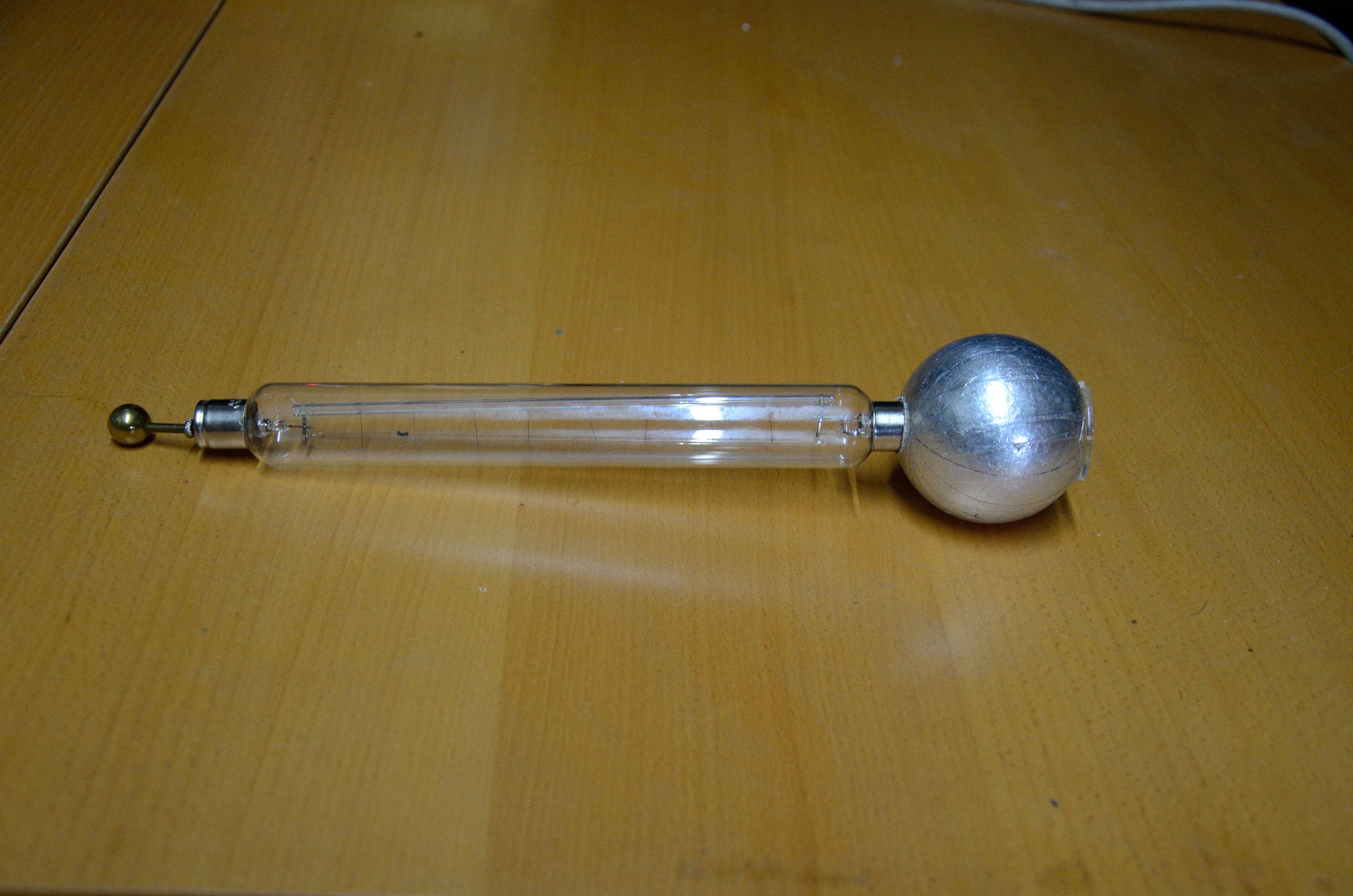
The large ball on the other end gives stability and stops the lamp from falling over.
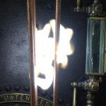
The stills from the video.


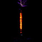
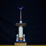
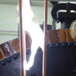
and the last one of the failed cap end..
External Links that I have found useful.
Laser alignment guide (Just add Sharks but applicable to most lasers)
0xFred All sorts of good K40 tips
So I bought a cheap Chinese 40W CO2 Laser Cutter and it’s actually OK (Part 3)
Mikes Electric Stuff – Cheap Chinese Laser cutter – A really early K40 blog
40 Watt Chinese CO2 Laser Upgrade with RAMPS & Arudino
Legend of the Cheap Chinese Laser Cutter – Applied Absurdity
My experiences Tales of a Cheap Chinese Laser cutter – Pre-Checks
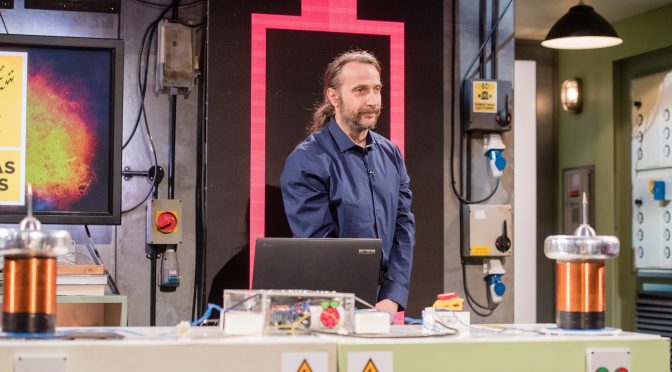
Earlier this month it was my great honor to be invited to demonstrate the PI zero tesla coils at the Royal institution Christmas lectures.
The Christmas lectures were a Christmas institution when I was growing up and they formed a great part of my education, especially the ones by Eric Lathwaite. This year is their 80th televised Christmas Lecture, I’m sure in that time it has inspired the lives of many many children to investigate science, and long may it continue to do so.
Behinds the scenes at the lectures was incredible, the organised chaos that was happening was untrue. There were 20+ experiments in the lecture (the first of three) and moving them in and out of the theater was a very well choreographed scientific dance.


I have every admiration to the RI and Windfall Films that produce it.
Walking in to the theater and standing where Faraday and not to forget, Tesla himself had lectured, I can’t explain the feeling. Oh, and the 350+ kids watching you… No Pressure…
The theater is incredible, it’s so much smaller than it looks on TV, add three cameras, a lecturer and 10+ support staff (dressed in black), it doesn’t leave much room for demonstrations that need a couple of meters exclusion zone for safety.
What will be featured on the lecture on Boxing day, not a clue, as is usual with any filming, its down to the final edit.
Even if I don’t make it on to the show, watch anyway well worth it for kids of all ages.
Behind the Ri Christmas Lectures- Show 01, 2016 Mark Parker – Standup Maths (warm up guy)
This Lecture is the first to go out BBC4 20:00 Boxing day 2016
The video is now available at http://richannel.org/christmas-lectures/2016/supercharged-fuelling-the-future