Category Archives: Uncategorized

Code to write to I2C YwRobot display from PI command

Compile with  gcc -o i2c_lcd i2c_lcd.c -l wiringPi

Usage:
i2c_lcd -i  init display
i2c_lcd -c  clear display
i2c_lcd -1:2:3:4 “text”  print text to line 1:2:3:4

#include <stdlib.h>
#include <stdbool.h>
#include <stdio.h>   /* Standard input/output definitions */
#include <string.h>  /* String function definitions */
#include <unistd.h>  /* UNIX standard function definitions */
#include <fcntl.h>   /* File control definitions */
#include <errno.h>   /* Error number definitions */
#include <termios.h> /* POSIX terminal control definitions */
#include <time.h>

char * lockfile="i2c_lcd.lock";
int i2c_address=0x27;
int fd;
bool backlight=true;
int last_data;

void init_lcd(void);
void I2CWriteDirect(int);
void I2CWriteDirectBl(int);
void lcd_strobe(void);
void lcd_write(int);
void lcd_puts(char *, int );
void test_write(void);
void lcd_write_char(int);
void lcd_clear(void);
void lcd_cursoroff(void);
void checklock(void);
void clearlock(void);
void AllLines(char * );

void main(int argc, char *argv[]){
wiringPiSetup();
if (false==(fd=wiringPiI2CSetup(i2c_address))){
fprintf(stderr,"Can't open i2c on port %i\n",i2c_address);

exit(1);
}

if (argc==1){
printf("Usage:\n");
printf("i2c_lcd -i  init display\n");
printf("i2c_lcd -c  clear display\n");
printf("i2c_lcd -1:2:3:4 \"text\"  print text to line 1:2:3:4\n");
printf("\n");
}

int i;
for (i = 1; i < argc; i++)  /* Skip argv[0] (program name). */
{
if (strcmp(argv[i], "-i") == 0)  /* Process optional arguments. */
{
init_lcd();
lcd_cursoroff();
}
if (strcmp(argv[i], "-1") == 0)  /* Process optional arguments. */
{
checklock();
lcd_puts(argv[i+1],1);
}
if (strcmp(argv[i], "-2") == 0)  /* Process optional arguments. */
{
checklock();
lcd_puts(argv[i+1],2);
}
if (strcmp(argv[i], "-3") == 0)  /* Process optional arguments. */
{
checklock();
lcd_puts(argv[i+1],3);
}
if (strcmp(argv[i], "-4") == 0)  /* Process optional arguments. */
{
checklock();
lcd_puts(argv[i+1],4);
}
if (strcmp(argv[i], "-c") == 0)  /* Process optional arguments. */
{
checklock();
lcd_clear();
}
if (strcmp(argv[i], "-f") == 0)  /* Process optional arguments. */
{
checklock();
AllLines(argv[i+1]);
}

}

clearlock();

//   init_lcd();
//   lcd_clear();
//   test_write();
//    lcd_puts("test string",3);
//    lcd_puts("Last line",4);
}

void checklock(void){
if( access( lockfile, F_OK ) != -1 ) {
printf("Lock Exists\n");
while(access( lockfile, F_OK ) != -1 ){usleep(10000);}
}
FILE *fp = fopen(lockfile, "ab+");
}

void clearlock(void){
if( access( lockfile, F_OK ) != -1 ) {
unlink(lockfile);
}
}

void I2CWriteDirectD(int data){
data=data & 0xFF;
I2CWriteDirect(data);
last_data=data;
}

void I2CWriteDirect(int data){
data=data & 0xFF;
if (backlight){
wiringPiI2CWrite(fd,data | 0x08);
}else{
wiringPiI2CWrite(fd,data);
}
}

void lcd_strobe(void){
usleep(400);
I2CWriteDirect((last_data | 0x04));
usleep(400);
I2CWriteDirect((last_data ));
//   usleep(400);
}

void lcd_write(int data){
I2CWriteDirectD((data >> 4)<<4);
lcd_strobe();
I2CWriteDirectD((data & 0x0F)<<4);
lcd_strobe();
}

void lcd_write_char(int data){
I2CWriteDirectD(((data >> 4)<<4) | 0x01);
lcd_strobe();
I2CWriteDirectD(((data & 0x0F)<<4) | 0x01);
lcd_strobe();
}

void test_write(){
lcd_write(0xC0);
lcd_write_char('T');
lcd_write_char('E');
lcd_write_char('S');
lcd_write_char('T');
}

void init_lcd(void){
/*   Port definitions
addr, bl,strobe,rw,rs,   d4,d5,d6,d7
0x27, 3, 2     , 1, 0,   4, 5, 6, 7
*/
//set 4 bit mode
I2CWriteDirectD(0x30); //write
lcd_strobe();
usleep(5000);
lcd_strobe();
usleep(5000);
lcd_strobe();
usleep(5000);
I2CWriteDirectD(0x20);
lcd_strobe();
usleep(5000);

lcd_write(0x28);
lcd_write(0x08);
lcd_write(0x01);
lcd_write(0x06);
lcd_write(0x0C);
lcd_write(0x0F);

}

// put string function
void lcd_puts(char * stringin, int line){
if (line == 1){lcd_write(0x80); }
if (line == 2){lcd_write(0xC0);}
if (line == 3){lcd_write(0x94);}
if (line == 4){lcd_write(0xD4);}

char buffer[22];
int a=0;
for(a=0;a<20;a++){buffer[a]=' ';}

a=0;
bool ok=true;
while(ok){
if(stringin[a]!=0){
buffer[a]=stringin[a];
a++;
if (a>19){ok=false;}
}else{
ok=false;
buffer[a]=0;
}
buffer[a]=0;
}

//  printf("Buffer %i:%s\n",line,buffer);

//  for (a=0;a<20;a++){
//    lcd_write_char(buffer[a]);
//  }
a=0;
while((a<20) && (buffer[a])){
lcd_write_char(buffer[a++]);
}
}

// clear lcd and set to home
void lcd_clear(void){
lcd_write(0x1);
lcd_write(0x2);
}

void lcd_cursoroff(void){
lcd_write(0x0c); //cursor and blink off
}

void AllLines(char * filename){

FILE * fp;
char * line = NULL;
size_t len = 0;
ssize_t read;

fp = fopen(filename, "r");
if (fp == NULL) {
fprintf(stderr,"Cant opem %s\n",filename);
exit(EXIT_FAILURE);
}

int l=0;
while (((read = getline(&line, &len, fp)) != -1) && l<4) {

int a=0;
for(a=0;a<len;a++){
if (line[a]!=0){
if (line[a]<' '){line[a]=0;}
}
}

l++;
lcd_puts(line,l);
}

}


Morse code test oscillator

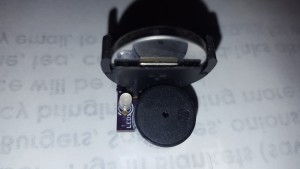
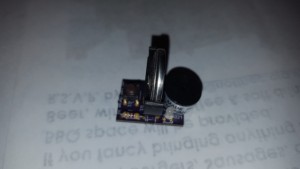
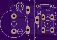
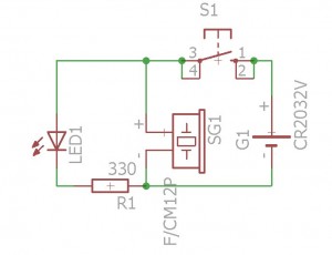
Simple Morse code test oscillator for Morse practice – A Simple (& cheap) soldering project


I designed this for a Scout group as a simple soldering project Electronics Badge and as part of the Communication Badge.

With care the parts can be sourced for under £2.50 each.

20160427_172802 20160427_172810 20160427_172820 20160427_172754

The boards can be ordered from OSH Park and cost £2.20 for 3
Order from OSH Park

MT MT2

Circuit

morse

BOM

1 x 3mm Led
1 x 1K(or 300R)
1 x Sounder (10 mm pitch) max diameter of 12mm
1 x CR2032 vertical battery holder
1 x CR2032/LR2032 battery
1 x Push button 5mm pitch x 7.5mm pitch

Some Electronic expertise needed, and of course a good soldering teacher.

This project uses Lithium Button batteries, please note the warnings here – Do Not short out the batteries, and Do Not swallow them.

Morse Code
315px-International_Morse_Code.svg

Morse Code decoding “tree”

Morse-code-tree

ALSO

If you wire two boards together (wire the two sounders together with a long bell-wire cable, be careful to get them both the same way around) you can make a telegraph system with a button and sounder at each end. Then you can practice sending and receiving for real….

CONSTRUCTION

Construction details are here


Lichtenburg figure test

Test of transformer choice and wood type for reliable Lichtenberg figures.

Obit – 20Kv 20mA

Both pieces of wood lightly soaked in water (only) just before test.

wood – 4mm MDF

20160420_190448 20160420_190445

Wood length 18″ – each pattern ~6″ across.


Course grained 3 ply

20160420_192526 20160420_192530

Burns only continued in line with the grain. Test abandoned.


Strontium breakouts

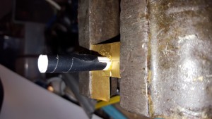
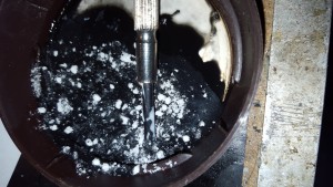
A test of breakout points made almost entirely of Strontium. The idea is that rather than containing the Strontium in a tube that needs to withstand the heat of an arc, we make a breakout with as much Strontium as possible. Of course Strontium is quite a good insulator so we need to add in a conductive component and something to hold it all together. This test uses PVC glue as the binder and bear conductive ink as the conductor.

tmp_24485-20160117_1901352034523555tmp_24485-20160117_1857471367784658tmp_24485-20160117_185517775580088tmp_24485-20160117_185414-1425974767

Initial tests on a large rotary classic tesla coil

DSC_1015DSC_1013DSC_1005DSC_1263_NEF_embedded


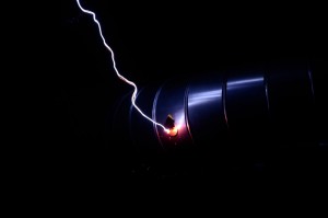
Some effect, but not as strong as Id hoped. Although the one on the chicken stick wasn’t bad.

SSTC 1Kw Much better results.


DSC_1097 DSC_1109 DSC_1111 DSC_1116

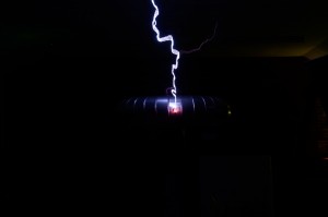
A great improvement on any other methods that I have used, and better still, the breakouts seem to be quite resilient and can be used multiple times.

Time to try other mixes 🙂


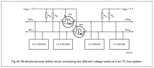
I2C to 5V slave using Pi zero

Just a link that says it all..

https://nathan.chantrell.net/20120610/raspberry-pi-and-i2c-devices-of-different-voltage/

You can connect 5V slave devices via I2C, although it will work, it’s out of spec.

Great trick to level shift using 2 resistors and two MOSFETS

i2c_level_shifter

Thanks to Nathan Chantrell for the confirmation that it will work.


High speed I2C on PI Zero

After playing with the I2C bus on the Pi Zero I found that I was unable to change the baudrate with either of the commands

modprobe i2c_bcm2708 baudrate=200000

or

gpio load i2c 2000

Apparently you now need to set the I2C speed in /boot/config.txt

Mine now reads:

dtparam=i2c_arm=on
dtparam=i2c1=on
dtparam=i2c1_baudrate=500000

Of course it does need a reboot to change.

Strangely dtparam=i2c1_baudrate=1000000

won’t work, but that may be due to my receiver and not the PI


V8 Tesla Engine

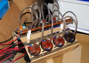
Img_20130615_771The V8 Ignition coils

Img_20130615_763A 30 Kv power supply using 8 car ignition coils. The output of the coils are rectified with strings of 40 x 1n4007 diodes.
Each ignition coil, run flat out, draws around 5A at 12V so in theory the output should be around 300-350W drawing around 40A from the 12V supply.

The advantage of this drive is that there is no mains to back any fault, so it does make using the supply (slightly) safer than a mains powered unit.


Img_20130615_767

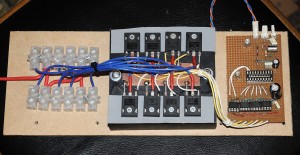
The ECU (Engine Control Unit)
The heart of the power supply is the ECU. The ECU gives some control of the output power of the system. The power is controlled by a variable resistor which controls the average power to the coils.

By arranging that no coils fire at exactly the same time as any of the others, the peak current draw from the batteries is limited, this allows smaller batteries to be used at lower powers. It also smooths the output so a smaller HV smoothing capacitor may be used. It effectively gives an 8 phase rectified HV supply.

To implement this there is a PIC18f14K50 controlling the timings of the 8 coils and taking control from a variable resistor. The PIC ensures that the on time of each coil is set to a maximum value ( 2.5mS for now can be as high as 3.5mS) so the coil will not be run into total saturation. It also spreads the pulses out over the 8 coils to prevent multiple coils turning on at the same time (except approaching full power where this is unavoidable.)

We have POWER!!! First test at full voltage 24v (2 x 12v SLA) into a jacobs ladder. Added 0.1uF caps across each of the coils to limit voltage rise when turned off. This is a much bigger problem at 24V than 12V. No clues at actual power. Well over 10A. My meter only goes up to 10A, and the fuse blows at 12A, I need a larger ammeter, and a new fuse. Continued in Strand on Tesla Coil

Tesla coil Slow motion Video using a raspberry Pi

After a suggestion by Phil T at Cambridge Teslathon I tried to make a slow motion video using my EMIpi

After finding the right command line for high frame rate from https://www.raspberrypi.org/blog/new-camera-mode-released/ I tried the 90 FPS at 640/480 pixels

As I had no way to view the videos I had no idea what I’d captured. Until after the Thon.

Returning home I found a problem. First I hadnt got a .264 player, and then when I played the videos they were at normal speed.

Reading up on .264 the frame rate isn’t encoded in the video, so the player will try to play them at normal speed. A quick google revealed the answer if you use a program called GPac https://gpac.wp.mines-telecom.fr/mp4box/ you can re-encode the videos at mp4 and re-sample them at whatever viewing rate you like.

This is my test video shot at 90fps and re-sampled at 5fps (1/6 real speed see below)

and the same video re-sampled at 1fps (1/30 real speed see below)

The actual speed in these videos is open to debate.

The first one should be 18 times slower than “real” and the second 90 time slower than real. But if that were true the frames would change one a second, and that is clearly not the case.

So my guess is that MP4box is assuming that the original video was 30fps (not 90fps) so setting a frame rate in MP4box of 30fps would give an actual speed of 1/3rd real. 10fps therefore would be 1/9th real, and 1fps would be 1/30th real.

I should be able to prove this as I know the break rate of the coil, and should be able to analyse the arc progression with each bang.

Downside is obviously the resolution.


I need to try the other modes.

  • 2592×1944 1-15fps, video or stills mode, Full sensor full FOV, default stills capture
  • 1920×1080 1-30fps, video mode, 1080p30 cropped
  • 1296×972 1-42fps, video mode, 4:3 aspect binned full FOV. Used for stills preview in raspistill.
  • 1296×730 1-49fps, video mode, 16:9 aspect , binned, full FOV (width), used for 720p
  • 640×480 42.1-60fps, video mode, up to VGAp60 binned
  • 640×480 60.1-90fps, video mode, up to VGAp90 binned

Although the higher resolution ones are probably not fast enough to capture anything interesting in a TC discharge.

Finally, Power from a tesla coil – Free energy?

2004_0728_210053aI have been tesla coiling for over 14 years now, and I have always believed that there was no way that a tesla coil could produce more power out than was applied in. Of course there are many stories of Tesla himself creating a power system from tesla coils, but these mainly refer to his “World Power System” which was a method of distributing power, not creating it.

Recently I have been experimenting with car ignition coils to create the high voltage required for the input to a tesla coil and have had great success with this for a number of small coils.

Whilst playing with this system, I noticed a strange phenomenon. If the ignition coil was close to the primary of the tesla coil some of the large current circulating in the primary would be induced back into the ignition coil, I could even draw spark from an unpowered coil near the working tesla 2003_0906_110312AAacoil.

Thinking about this further I decided to put the ignition coil upside down into the secondary of the tesla coil and draw out the HV lead out and feed back into the spark gap and the unmodified primary coil / capacitor of the tesla coil. If I gave this circuit a high voltage pulse to start it, the tesla coil would power its-self for periods of up to a second.

Obviously2003_0923_220336AA I needed to reduce the losses in the coil to maintain the process.

After much playing, I can now get the tesla coil to run for fractions of a year with no extra input and with instantaneous outputs in the region of millions of Ergs per second.

One drawback to this process is any tools in the vicinity acquire a blue glow which is really difficult to remove , they also give a nasty spark when you touch them.Img20081121-214320aa

But, this important thing is, can I extract any useful power from this arrangement?

Looking in to this I attached a common kettle and unfortunately found that the device won’t power it efficiently due to the differences in the voltages needed compared to the high voltages generated , but I have used the coil to create heat directly creating temperatures of thousands of degrees C, well in excess of the temperature required to boil water, and that could be used to power a steam turbine.

For now I will be keeping this power source’s exact details a closely guarded secret, as I would like to make millions from it, not just run my house. My prototype is happily powering my LCD clock and has been for a number of days, although I do need to clean the electrodes from time to time to maintain this level of power, so far I haven’t found a non-corrosive element better than lemon juice to keep them clean.

Img_20130615_771

Next is to scale up the process.

Unfortunately I can’t get larger ignition coils, but I can get multiple tesla coils, and I’m starting to build a system with 8 coils. At present I can get about 300W at 10KV with this system, although it is being driven at 24V at present.

But to be able to draw 10KV from the machine is a great step up from only 24V. 10KV is not far from the voltage(14.4kv) used in small power transmission systems that power small industrial parks, not bad from a couple of small 12V batteries.

For more details, take a look at the V8 telsa engine https://www.extremeelectronics.co.uk/other/V8TeslaEngine/