

 |
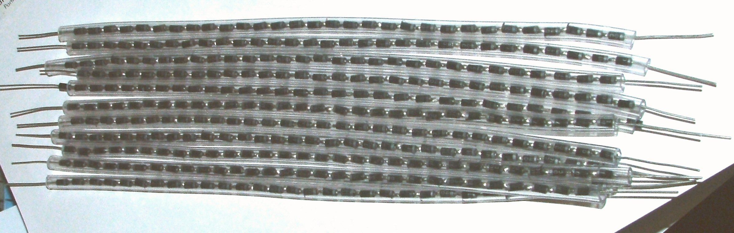
Cockcroft Walton Voltage Multiplier The project worked very well indeed, It leaked electricity from every un-insulated point, but I got a decent voltage from the top. This was fine untill I got too close with an earth and discharged the bottom capacitor through the bottom set of diodes (they selflessly gave themselves up to the cause). So from this earlier success I wanted to use all of my 8 Capacitors and ordered a stack of diodes. This time I went for the BY8408's as they are rated at 8KV 5mA, but used a stack of four in each stage giving me a per stage over spec to 32Kv. Each stage is insulated with silicon windscreen washer pipe, and the whole construction is (for now) taped to a peice of 1" trunking. The
output of the stack is protected with 10 x 1M 3Kv resistors (well
they are flash tested to >9Kv each !!), and a set of 3 for each leg of
the OBIT, to reduce charge up inrush. Results. Wow, this thing will charge me up to more than 70Kv from about 1' away (I know this as I was standing on a 3" length of pipe and could feel arcs to ground through my feet.!!). Flourecent lights light near it, It's like having an evil VDG, but with no moving parts.. |
 |
Experement 1 Bouncing Ball A polystyrine sphere, coated with aluminium foil, and
suspended from a cord, as the power is applied the ball charged to the
same potential as the sphere and thus is repelled. As the charge leaks
away, the ball again touches the sphere, is charge etc... |
 |
Experement 2 Levitation A polystyrine
sphere, coated with aluminium foil is placed on the terminal, as the power
is turned on the sphere is repelled, it floats off the ball. Click Picture for movie. 289kb |
 |
Experement 3 Ion Spinner A ion motor, made from a bent peice of copper wire, placed on a crude bearing. As power is applied the sharp ends of the spinner blow ion wind, pushing the spinner around. Click Picture for movie. 375kb |
 |
Experement 4 Hair Raising A wig is attached to the terminal, when power is applied the "hair" is all charged to the same potential, so each strand repells its neighbours. (The stand is the top of an abandoned project a rotary VDG .) Click picture for the power on image.. |
 |
Experement 5 HV Pie Cases A pile of pie dishes is stood on top of the output terminal
Click picture movie . 589K |
 |
Cockcroft Walton Voltage Multiplier II So I added another 4 stages (8 caps, 8 strings of diodes) This should give me a theoretical 200KV .. The first problem was that to protect the diodes, I had a string of 1M resistors on the output of the old CWM, this gave me a 20M @ 60KV , underated even then, It now would have to handle 200KV, a rebuild was in order. After asking around, the general idea was to use a pipe full of water to give me the value I wanted. After much experementation I managed to get a 20M resistor built with a 30" peice of 5mm ID silicone tubing wrapped around a 13mm former. The resistor was hard to measure, as the copper/water junctions gave about 0.15V, which totally confused my DVM. I eventually used a 24v supply and measured the current that the piping took across this, which gave me a more accurate reading of its resistance.
The picture is of the CMWII with the outer cover and top sphere removed. |
 |
The finished safety resistor. |
 |
On powering up the CWM stack, a loud crackling was heard I had acheived breakout on an 8" diameter sphere, It worked!! |
 |
By using a small machine screw I could get some excelent discharges to the air.
|
 |
I then started to play with another eqarthed 6" sphere about 10" away from the CWM's top sphere, I got some really nice arcs between the too. I then got a single really loud bright spark, followed by nothing.. $%^$K!!! |
 |
I found the damage, four of the HV diodes had blown, when the arc happened. these have been replaced, but I need to find out how the arc got past the safety resistor. I suspect either I'm getting more than 200Kv or the arc tracked along the inside of the outer pipe covering the CWM bypassing the safety resistor. |
 |
To prove that this CWM was an
inprovement on its predicessor I tried to levitate a 1
1/2"
polystyrine ball covered with aluminium foil. Previously I could only
levitate a 3/4" ball, and then only with small strips of aluminium foil to keep the weight down.
|
 |
After
various plays with the CWM, I
found that it was rather easy to get a spark big enough to blow the rather
flimsey 5mA rated BY8406 diodes. So I started to hunt around for
some better ones. The 30KV diodes broke down at around 10KV, my ebay bargin wasn't quite so good and having only 20 diodes I didn't have enough to double them up. After a lot of searching around for replacement diodes, I eventually came to the conclustion that cheap off the shelf doides were the way forward, and bought a large pack of 1N4007's these are 1000V 1A diodes and cost me about £0.01 each , so a string of 30 would do for a single stage, 16 stages, 480 diodes would do the job.
|
 |
To ensure
that I could get all of the string
soldered neatly, I made a jig from two peices of MDF spaced 4mm apart with
a diode sized hole in each. Each diodes leg was cut to 4mm long, and one
by one threaded through the jig and soldered together in the gap in the
center.
|
 |
Each String was
connected and wound around the "diode" leg of the CWM . The next trial is to reduce the charging resistors as now I can take up to 1A arcs... |
 |
Ok, So I had a little play. I haven't tried the experement with the wig with the 16 stage setup and I thought it worth a try. Click the picture to find out what it looks like with power..
|
| Next ---> The CWM continued.... |
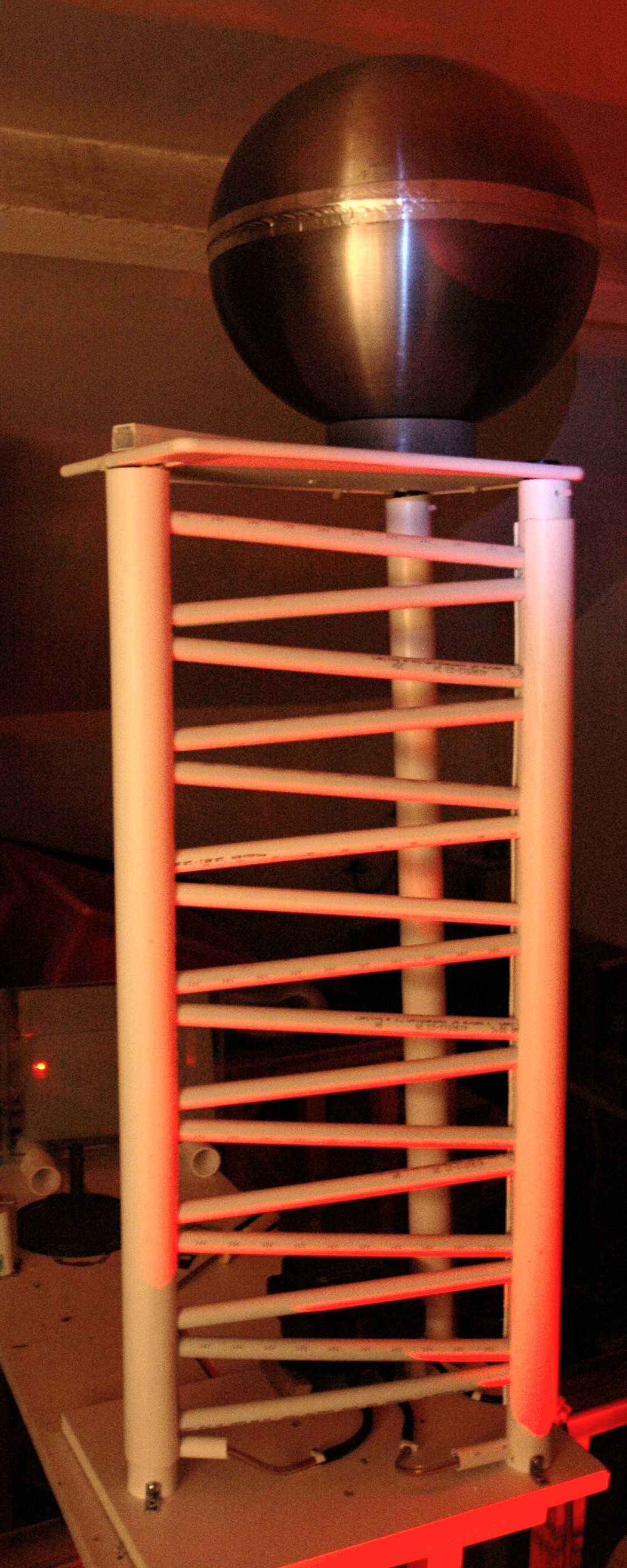 |
Cockcroft Walton Voltage Multiplier III The capacitors are contained in a two pipes, the inner pipe has holes drilled on either side to allow connecting the diodes and capacitors, the second pipe fits as a sleeve over the first to prevent corona. The top ball is offset to allow for the fitting of a safety resistor (not fitted). On powering up the stack it is much more efficent, I think this is due to the reduced leakage between stages. Unfortunatly I have a single cap that is rather weak, and if running the stack with no load it arcs over its entire length, I suspect either im getting more than 25Kv per stage or there is a tracking path on the case of the cap for this to happen. |
 |
Ive picked up a couple of caps that ive got to try to charge........ In series I think .. |
| Next ---> The CWM mk 4.... |
 |
Cockcroft Walton Voltage Multiplier IV
Yep, another rebuild, |
 |
Diodes |
 |
Capacitors |
|
|
With the addition of a water wouund resistor, similar to the one created earlier I can charge the two 200pF 100Kv Caps. |
 |
So First light at Cambridge Thon, This was actually the first time I had had any power into the multiplier. |
Incomplete 3 stage CWM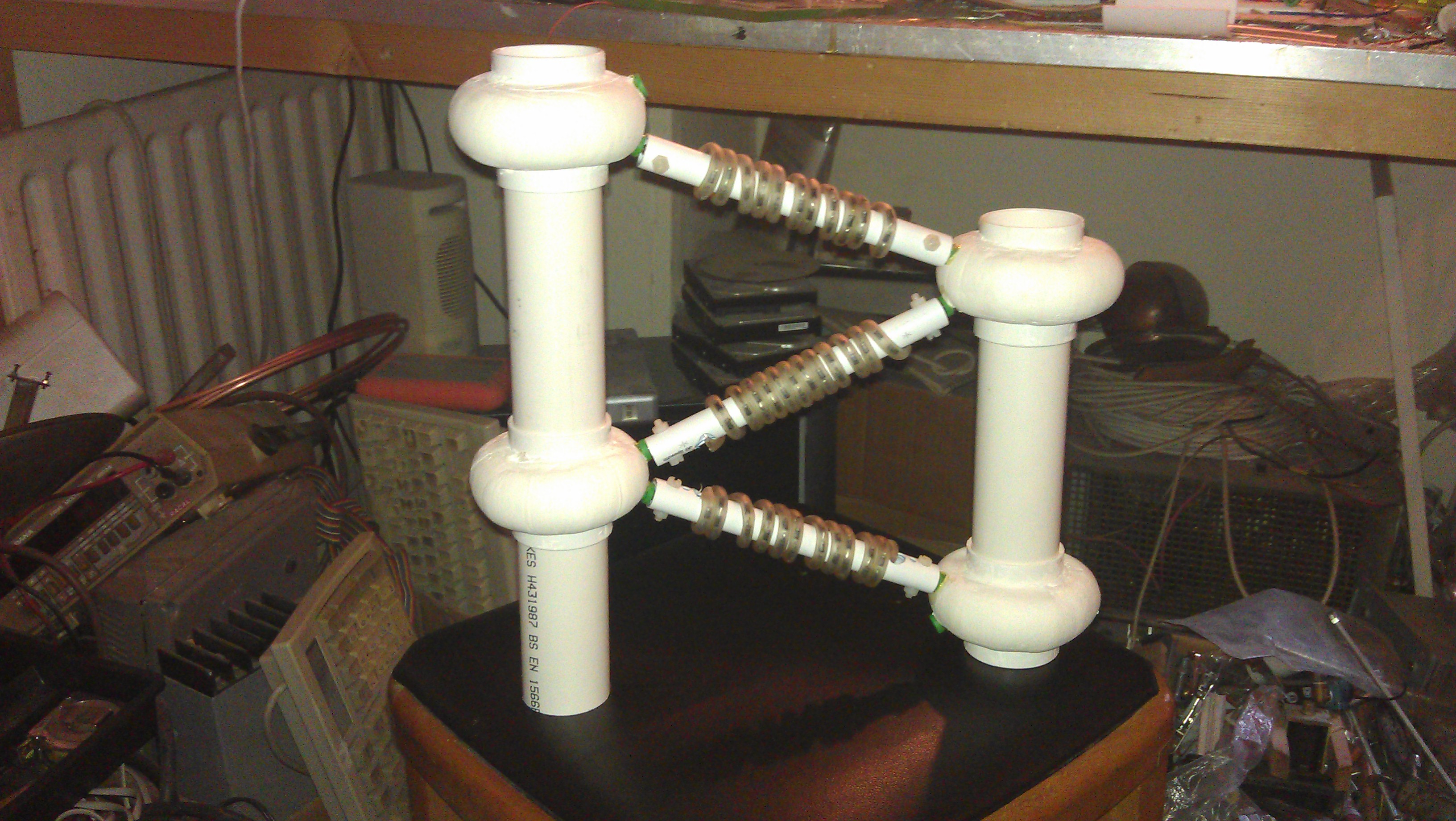
|
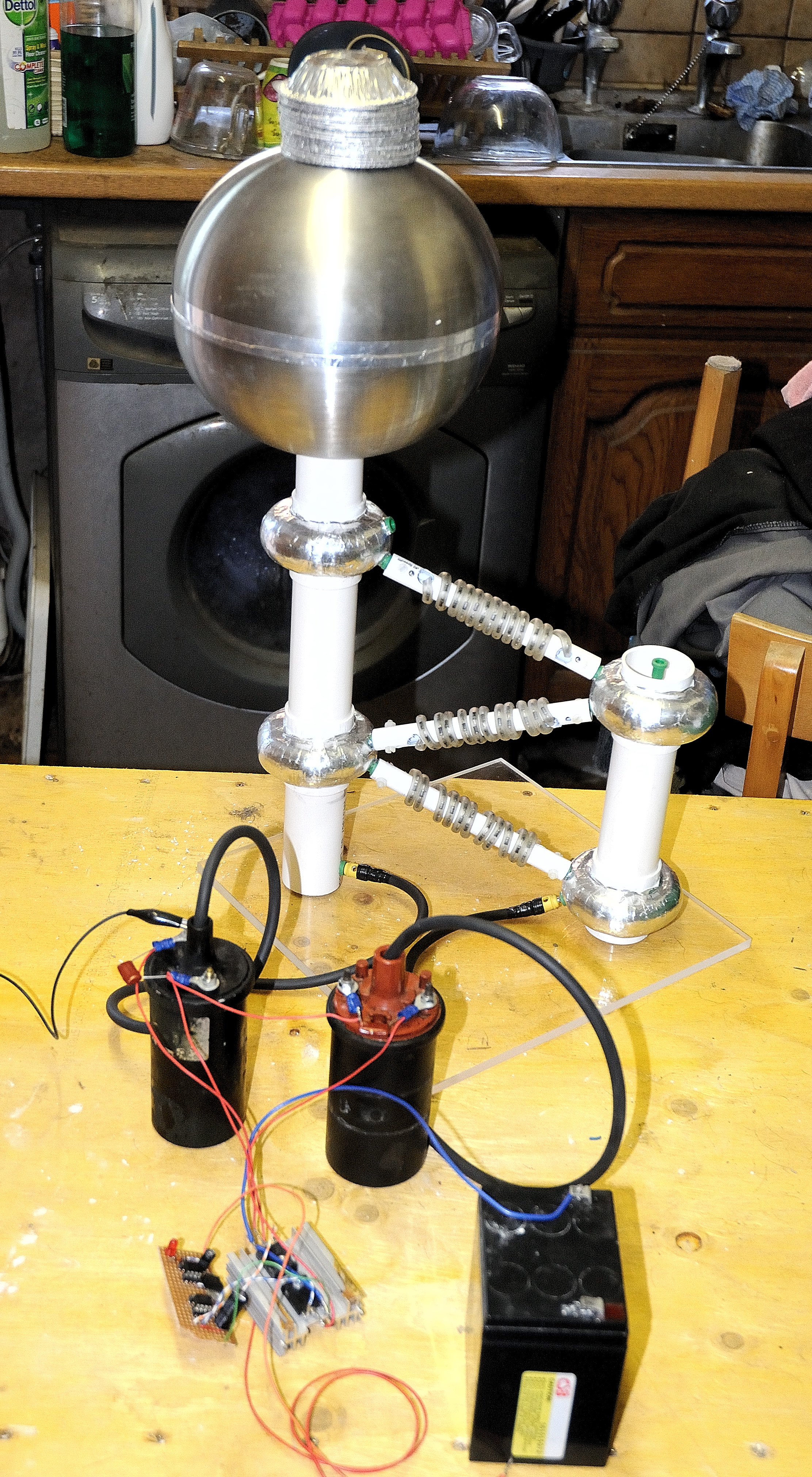
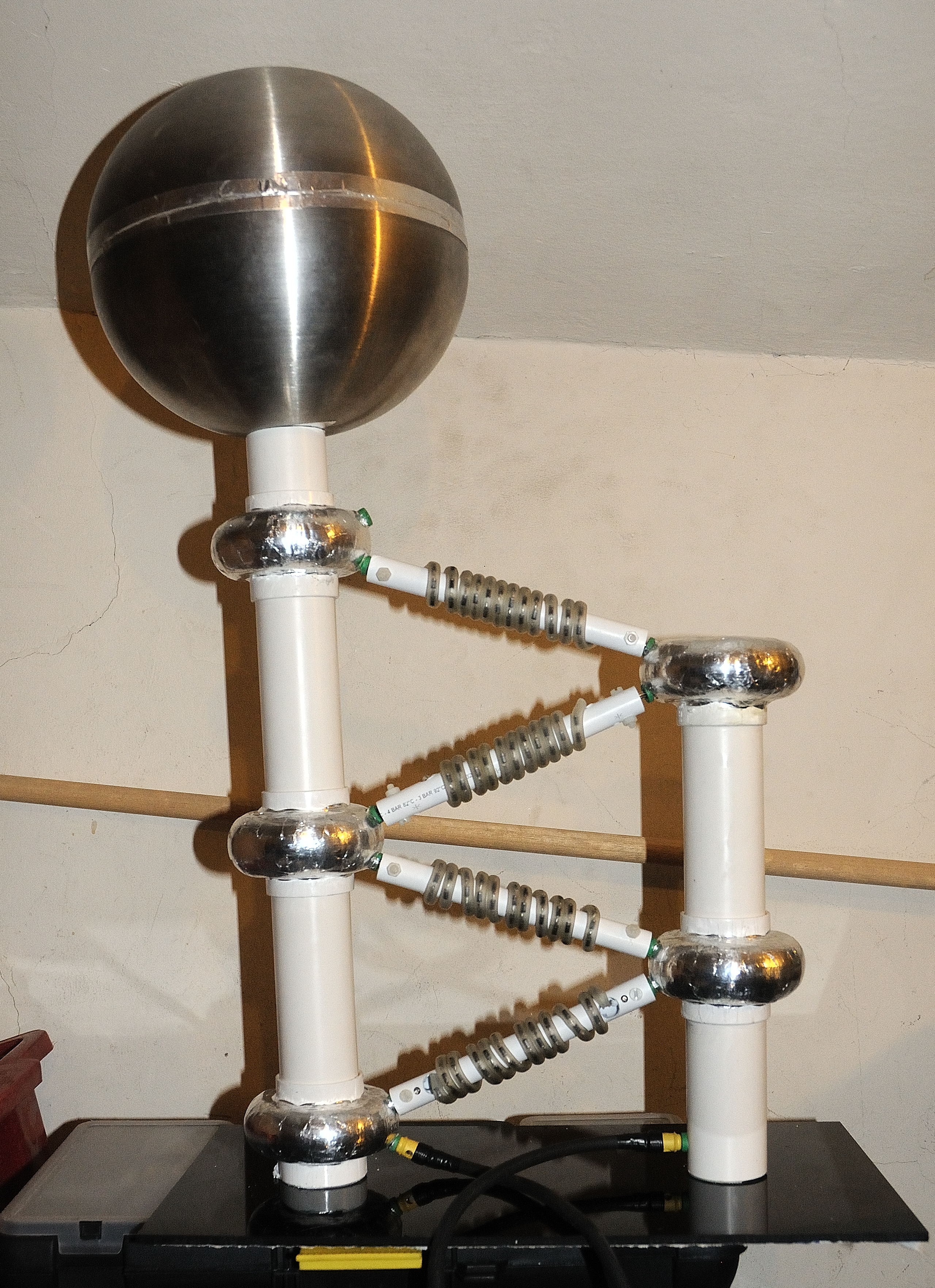
Cockcroft Walton Voltage miltiplier V3 |

|
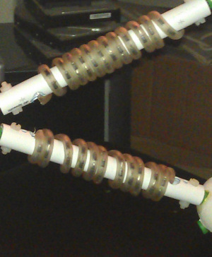
Each capacitor leg of the multiplier can take 120KV (apart from the first that runs at 60Kv) |
|
The diodes are in strings of 70 x 1N4007 giving 70KV per diode string. |

|
The anti corona "lumps" are made from air clay and are covered in aluminium foil to reduce corona at the joints. |

|
Each has 2 x 4mm socket connectors for the diode strings and another socket for the next string of caps. |
|
|
The stack is fed from a car ignition coil (or two later) that is run to give 30-40Kv (60-80KV for the pair) at about 25W (50W in a pair) |

|
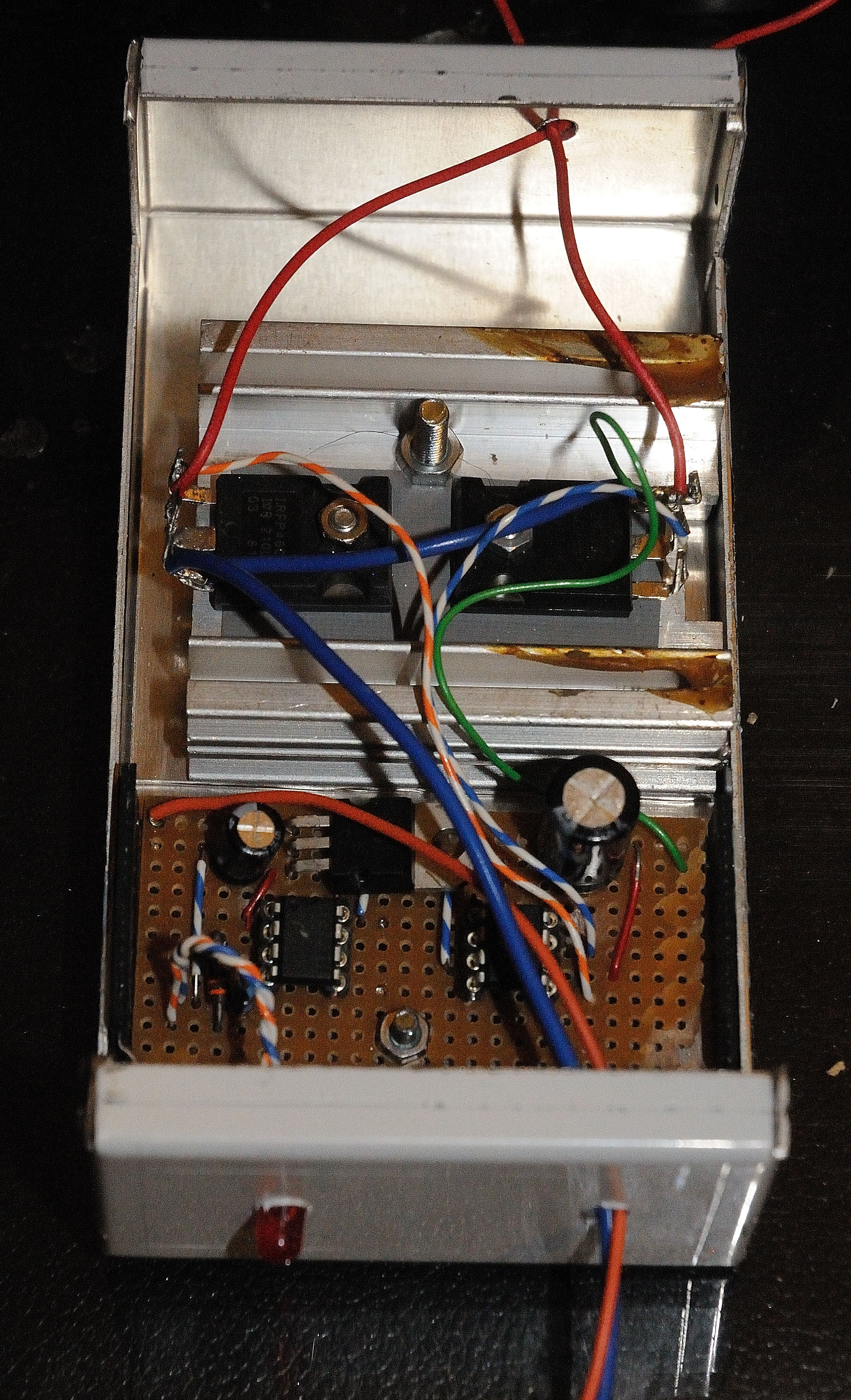
The ignition coils are fed from a bridge driven by a pic 12F510 |

|
The circuit above dosen't work. The kick back from the coils distroys the high side driver. Clamping the pulse causes a very poor output. So the bridge idea has been scrapped. |
|
First test setup. Pie dishes are to prove high voltage output. |
|
Finally 4 stages (mostly) complete and a base for the multiplier |

|
300V driver put on hold. |
|
Too late, I overvoltaged it... |