I recently came across the book Electrostatics by A. D. More online which featured a modern (1975) electrostatic generator called the Dirod Machine.

This is the same book that I got the idea for the folded shakesphere machine, that works in a similar way to the Dirod machine.
The images in this book online were hard to make out, so I’ve been waiting to get hold of an actual copy of the book and until recently they have been extremely expensive.
I now have managed to get a copy of this book without a leg or arm sacrifice, so the build begins.
The Dirod machine is an influence machine similar to a Wimshurst machine, but instead of sectors it has rods, and only one rotor. In many ways it is the reverse of a Franklin motor explanation here .
The rough diagram for the machine

and a 3d view as the basis for the one I built.
Operation
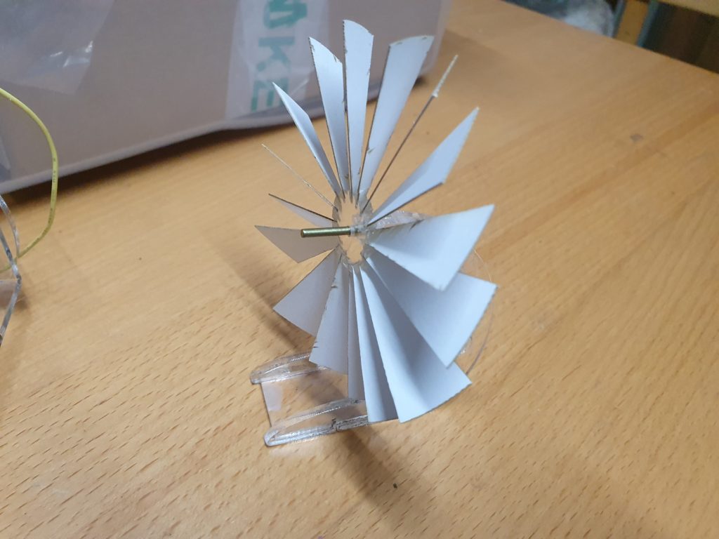
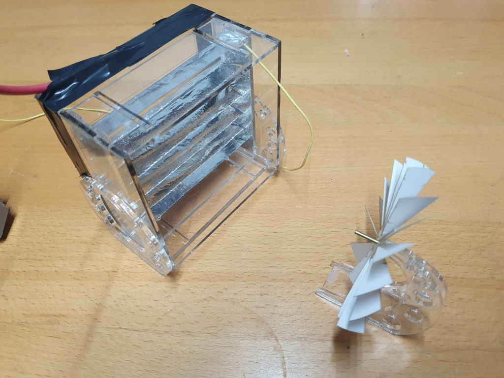
The Dirod machine consists of a rotating ‘drum’ made from an even number of rods held in place by a pair of acrylic disks that rotate on a central shaft.
At each side of the “drum” is a conductive plate with a brush that lightly touches the rods as they move past. These plates will become charged as the drum revolves, and the charge from the rod is added to the charge on the charge collector as the brush contacts it. The charge collectors on both sides of the machine is where the output is taken. As the machine is symmetrical, the polarity of the charge building on a specific plate entirely depends on start conditions. Any residual charge imbalance is just amplified by the machine.
As the machine is mostly made of insulators, there is always some charge (however small) to stat this multiplication process.
Moving with the direction of travel of the rods from the charge collector, the rods pass under an inductor plate that is electrically connected to the charge collector and the rod is earthed by a neutralising brush that discharges the rod, by shorting it to the diametrically opposed rod that will have an equal, but opposite charge.
After the rod has been neutralised it will gain a charge from the inductor above by electrostatic induction, this will be of an opposite polarity to the inductor. The now charged rod will continue around to the opposite charge collector, sharing its charge and completing the cycle.
As the rods under the inductor become charged with the opposite polarity to the inductor, a voltage equal to the output of the machine will develop, this can be in order of 200Kv. To prevent this from arcing and shorting the machine, a shield is needed to prevent the charge on the rod from arcing to the inductor. This is achieved by a shield of acrylic between the rod and the inductor. As 200Kv can jump 60mm or more across a surface this shield needs to extend a long way past the inductor.
The “drum” of rods has a central axel and is mounted on two ball bearing races, and is driven by a 300RPM geared motor with a speed controller.
Construction
For my Dirod machine I chose 200mm long Aluminium rods. Each rod needs the sharp edges at the ends smoothing off, and a rubber cap gluing on to reduce the leakage from corona.


24 of these were glued into place on to two 3mm laser cut 150mm discs of acrylic. Which were attached to a central 6mm stainless steel axel with 3d printed bosses.


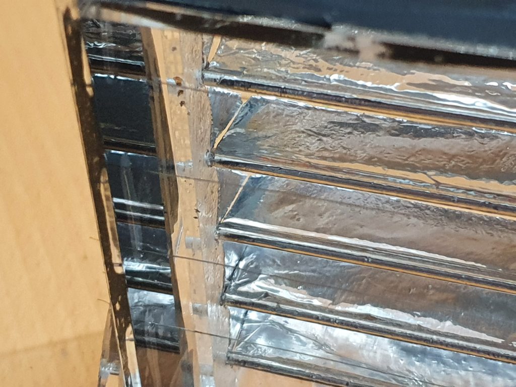
The Charge collectors and the inductors needed to be quite thick, and rounded to reduce corona leakage, so were 3D printed and covered in foil.


The Charge collectors differ to the inductors in two ways, one they have a 6mm hole in the top for the connection to the discharge balls, and they have a brush to collect the charge in the centre.


Initially I had all of the brushes made from brass shim, but after a short amount of usage i noticed that they were work hardening and starting to fail. Eventually I replaced them with conductive cloth backed with a strong repair tape. This gave them enough spring to connect with the rods as they went past with enough flexibility not to impede the rotation of the “drum”


The cloth brushes were also used on the neutralisers. Each nutriliser consisted of a 50mm stand-off with a brush glued in to place, connected through the end Acrylic to an aluminium coated bar that goes around the central shaft. All of the brushes were trimmed to contact the rods for only half of their diameter to limit the amount of movement required as the rods passed.


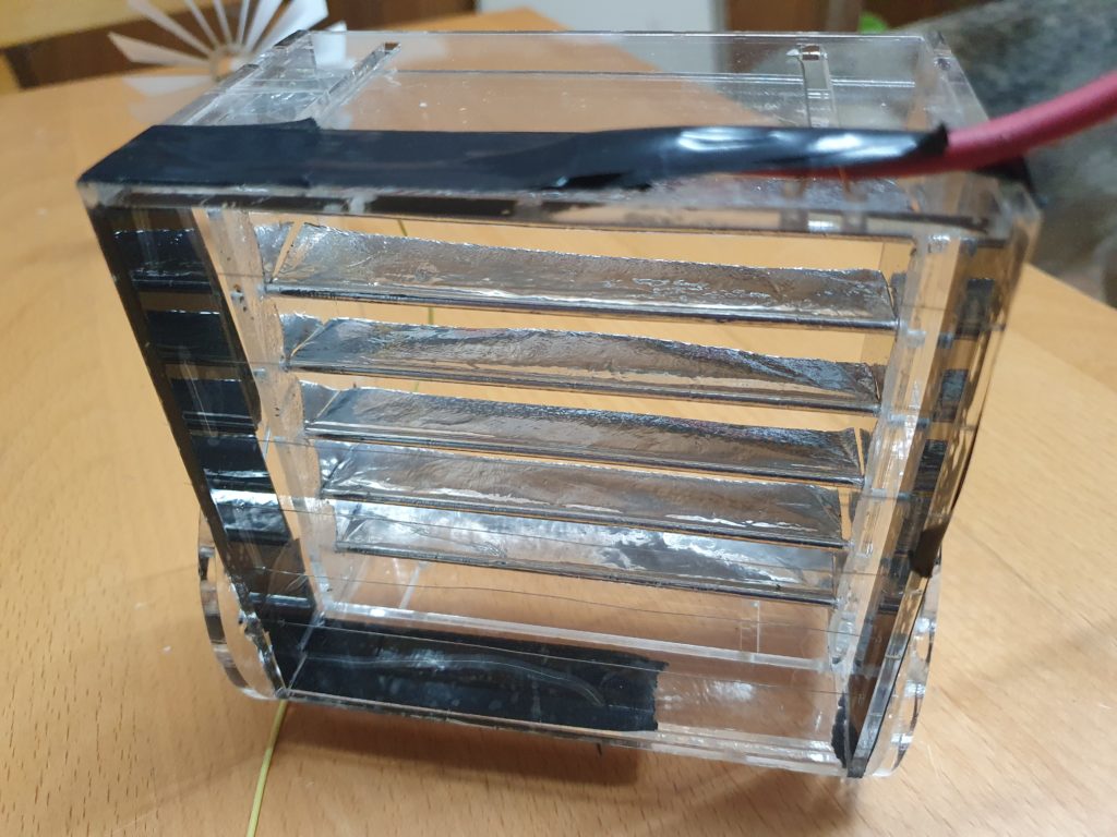
The Collectors and the inductors were glued into place on to the acrylic frame. The connection between the collectors and inductors was with a 3d printed element coated in foil, to ensure the minimum diameter of 12mm was maintained.


To prevent the insulation of the acrylic frame by conductive screws, the whole assembly is held together with acrylic wedges. The charge collectors (left and right) sit on the inside of the frame, whilst the inductors (top left, and bottom right) are glued to the outside of the much larger acrylic sheet, so this also acts as the shield.
Also note in the image above the neutralising bar has been reduced to maximise the stand-off voltage )in operation.
Two 6mm rods were bent over at 90 degrees and have 25mm balls to use as discharge balls. The rod is covered with PVC pipe as its diameter is too small to prevent a large amount of corona leakage on their own. The rods are loose in the charge collectors to allow for the gap between balls to be changed.


The “drum” is driven by a 12v 300RPM motor from a 12V source (usually a battery) To regulate the speed there is a speed regulator PCB under the motor. The motor is attached to the central shaft by a universal joint and the shaft sits on two flanged ball bearings attached to the acrylic frame.
Amazingly it worked first time, Even turning the “drum” by hand produced noticeable electricity.
It maxes out at about 60mm sparks, in really dry conditions. which relates to about 180Kv which is really not bad.
Dirod v Wimshurst
Comparing a 300mm Wimshurst machine with a 150mm x 200mm Dirod machine.
| Dirod | Wimshurst | |
|---|---|---|
| Voltage | Higher, due to greater current | Lower, except in very dry conditions |
| Current | Much higher, but its physically larger | Lower, but smaller in size |
| Build Good points | The tolerances are less exacting, single axle drive make simple mechanics. | High voltage points are not near mountings, no part of the machine has the entire output across it. Easier to add capacitors |
| Build Bad Points | Bigger and relies on good insulation of shields, high voltage near mountings/base. A lot of work to prep rods. Double the number of Brushes, | Contra rotating disks difficult to drive. More exacting tolerances . A lot of work to prep sectors. |
| Rods v Sectors | Harder to clean, more noise when working , much harder on the brushes. | Brushes are harder to maintain. Sectors are easier to clean, |
| Efficiency (subjective) | More | Less |