

 |
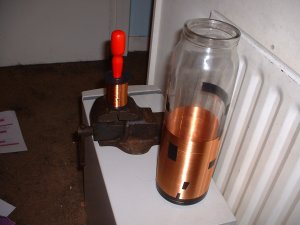
OLTC (Off line Tesla Coil) Off line Tesla coil. Runs direct from the supply voltage and has no hv step up transformer. The
Primary coil 2 coils of 2
turns of 5mm copper tubeing . The Secondary 2100 turns 0.125mm enameled copper wire wound on a glass storagejar 4" in diameter. Drive 2 x IGBT's Output 12" Sparks from about 200W in.at 2Khz. BPS 100hz - 2khz Circuit Diagram (not complete and subject to change) The Second working OLTC in the UK see http://www.scopeboy.com Steve Connors site for the first (and probably the third by now) OLTC primary Calculator Web tools to help design an OLTC |
 |
Half way through winding the
secondary |
 |
Close up of the primary coil, caps and IGBT's |
 |
It works, It needs some work, but it works. |
 |
Some more playing, re-built the driver to overdrive the IGBT's as per origonal OLTE spec. Adjusted the height of the secondary to change the coupling. This ment that I could tune the coils more accurately. Much better output 3-4" into air , 6" long sparks to earth. |
 |
I Then I
upped the BPS to around 1Khz, It ran fine for a while, until an arc
started between the dequeueing diode and the transorb across the charging inductor. Whatever happened I have an IGBT , transorb and a diode to replace, so time for a minor rebuild and the addition of a small fuse in the charging circuit after the capacitor to prevent it from happening again. The Failure was caused by a trapped wire in my control box adding 50hz to the gate drive for the IGBT's, Hopefully this won't happen again. |
 |
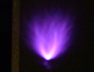
After Various component replacing & problems I got it running again.Two things became obvious, The turn off of the igbt's must happen accurately at zero voltage otherwise the losses are large and the coupling from primary to secondary is very important. To adjust the coupling I added various sized "chocks" under the secondary until I got maximum output, The "on time" of the igbt's also needed adjustment as the coupling changed. I changed the variable for the "on time" adjustment to a 10 turn pot, this allowed for much more accurate setting. After reaching about 6" sparks (with running sparks down the coil) I decided that I still hadn't got the tuning right. By adding another topload I proved that the primary cap (1.88uf made from 4 x 0.47uf's) was too large, so I removed a 0.47uf and replaced this with 4 x 0.1uf's, (better) and then 3 x 0.1uf's even better. 2 x 0.1uf's did not improve the output so I stuck at 3 giving me a primary cap of 1.71uf. The picture to the left is running at 2khz and the arc is at least 12" to air. The noise from the arc is deafening. (See move further down) |

 |
12" spark to air |
 |
12.5" arc to earth |
| For the technical, two
traces. Top trace is from a scope probe about 1M away from the coil. Not actually connected, just the probe. The second trace is the voltage across the primary capacitor, note the charging to around 600V and the 2.5 cycles of oscilation before the transistor is turned off. (Only shows 2 cycles due to the triggering delay of my scope) ( |

|

|
Click picture for a movie of My OLTC "testing" a computer mother board. |
 |
AD-OLTC (Alternate Drive - Off line Tesla Coil) Alternate Drive - Off line Tesla coil. An upgrade to MY OLTC too double the power. The
Primary coil 2 coils of 2
turns of 5mm copper tubeing . The Secondary 2100 turns 0.125mm enameled copper wire wound on a glass storagejar 4" in diameter, 11" tall.. The Topload 10" Stainless steel sphere. (Two salad bowls from Ikea, but don't let on) Drive 4 x IGBT's, fired Alternately in pairs. Output 21" so far BPS 10hz - 10Khz Circuit Diagram (not complete and subject to change) OLTC primary Calculator Web tools to help design an OLTC |
  |
The New
controller , To allow for driving the IGBT's alternately, I had to
construct a new driver. As I was making a new driver I thought I may as
well include all the features I may need in the future. |
  |
Close up of the primary coil wiring and IGBT's all "wired" with 5mm copper break pipe. |
  |
Traces from inital testing at low voltage In each picture the top trace is Primary Capacitor
Charge and the The Top Picture is the coil running at low frequency around 200Hz. The bottom picture is the coil running at 4Khz showing some strange charging problems, and the bangs happening before the coil has stopped resonating. These two observations are probably connected. As the effect changes at different high BPS as if the oscillation on the secondary is becoming out of phase with the next bang on the primary. The bottom trace also shows that the charging inductor needs to be of a smaller inductance, to charge the capacitor up faster. This may also increase the charging voltage by flyback effect. |
 |
A new topload from Ikea, now 10" in diameter (was 8")
means that I can now use a 2.45uF primary cap. |
 |
I've added
a new Charging choke, to give me a quicker charge, and a little more
voltage on the primary caps. It also is giving me much longer sparks at
lower BPS's. The new choke is 2.5mH, made from a whole real of 1.25mm
enammeled wire. I had to wind it to fit the space available 1" x 3". |
 |
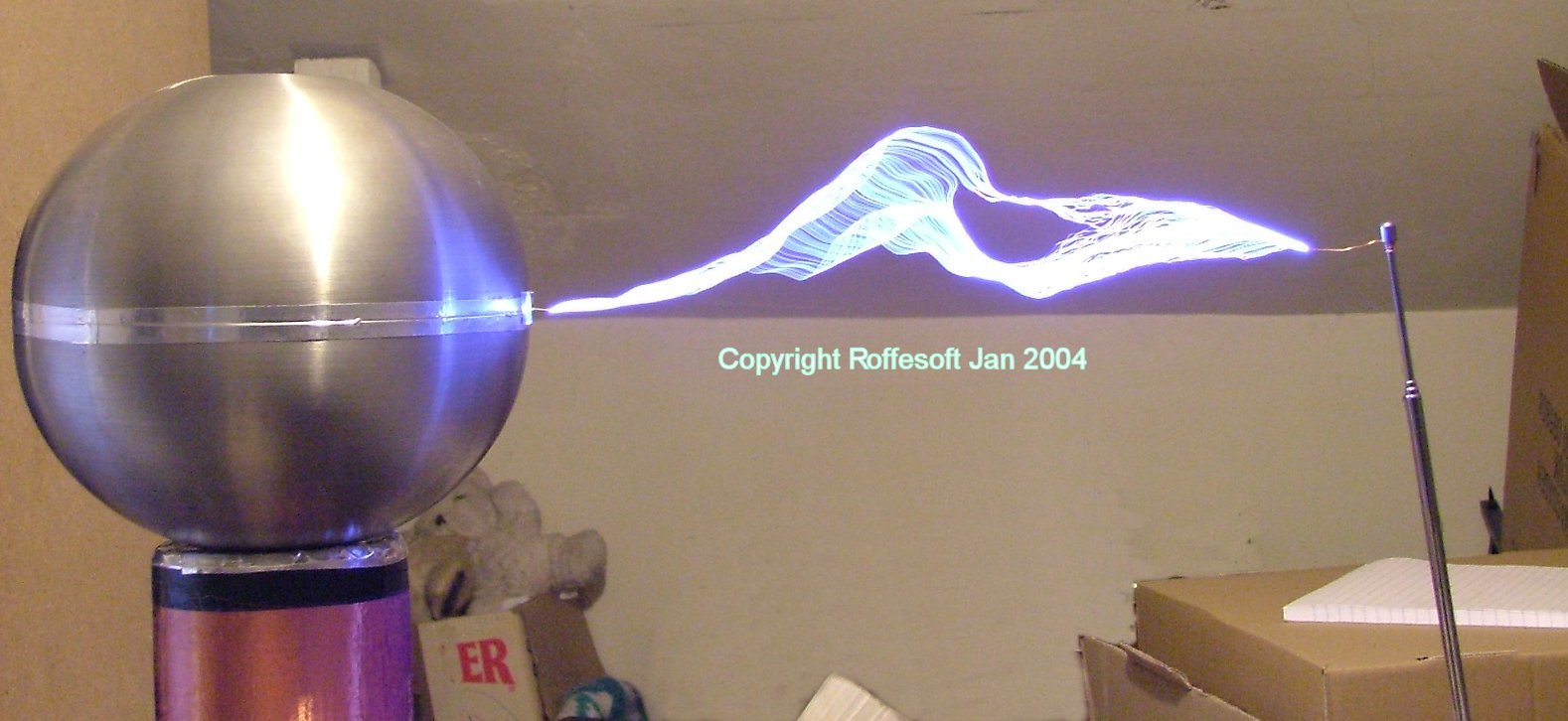
After the choke change I found
that the coils performance had increased. I had set up and earthed
rod with 1" of wire pointing towards my coil at the top the gap was
set at 20". The strike directly to the rod at the bottom of the
picture must be 21" at least. (I put this down to gravity 🙂
) Next a test of TT mode..... |
 |
TT mode
Running, At the Derby Teslathon. |
 |
Running at
the Derby Teslathon I had loads of problems with strikes to the mosfets
and strike rail resulting in the damage to the secondary. |
| <---Back The OLTC |
 |
AD-OLTC The Rebuild... So after blowing up the AD-OLTC I though it was a good time, not just to repair it, but rebuild the HV side. So.. Things that needed inproving.. The Coil The size
of the old coil was 11" and I was getting 21" sparks.. And them I'm
supprised when it arced over ? 😉 .. Here is the coil 3/4 wound, I would it by hand, the tape is to prevent the coils from loosening if I let go.. To keep things simple I decided to wind the coil on 4.25" PVC waste pipe. |
 |
The
Primary The primary is held high so that all of the other components can be underneath it. This allows for a strike rail, and an insulated disk around the base of the coil. Im going to try a single primary, as this simplyfies the wiring, and I beleive that the current sharing in the IGBT's will be OK for one of them not to take all of the load. This also gives me the option of firing them all in parallel if required.. |
 |
The IGBT's Close up of the primary coil wiring and IGBT's all "wired" with 5mm copper break pipe. The IGBT's are wired in a much simplified way. This allow for easier changing of dead ones. The connections are deliberately "Z " wired, to reduce inductance, and to ensure that there is the same current flowing in each IGBT. |
 |
Sanity Check The finished Secondary coil has 1970 turns, and I have applied 5 coats of varnish. In this picture I had just rubbed down the coil between coats, hence the appearance.
|
 |
Replacing Blown
Silicon. When I took it apart it looked like there had been some power flowing through it. The only wat this could have happened is if it had touched the earthed case. (The electronics are referenced to bridge rectified mains 0V not earth). So I need to check the insulation from the slider to the case.. |
 |
At the moment I have 2x0.47uf and two 0.47uF's in
series and a 0.1uF giving me 1.275 uF |
 |
I started with the set of capacitances I had with the old OLTC around 2.5uF, As I tuned It was obvious that the capacitance would need to be smaller to bring the coil into resonance. I ended up with 1.5uF a whole 1uF lost.
|
 |
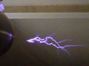
I took this
picture whilst tuning to show that at high BPS |
| <---Back The AD-OLTC | Next ---> The AD-OLTC continued.... |
 |
AD-OLTC Continued So
Amberley Teslathon happened. The OLTC ran quite well, untill I had another
problems with the controiller taking out the 4046 again. I beleive this is
caused by a spark jumping from the operator to the slider of the power
control. This is connected directly to the input of the 4046 so blows the
chip. Im going to try two diodes to the supply rails to hopefully shunt
this away to somewhere safe. The IGBT's are still running hot and im not getting the spark length I should be. I need to increase the coupling, probably by allowing the secondary to drop down into the centre of the primary. |
  |
I replaced the 4046 and 4011 again, and I've put in two diodes to the supply rails and a 0.1uF capacitor on the VCO input to the 4046 to prevent a strike from killing the IC again. (I'tl probably kill something else now.) I've found a circular sandwich box, that has a diameter of 140mm for an external primary to give me enough room to sink the secondary below the primary. 140mm is a slightly larger primary that I would have liked , but it was the best I could find, So I have wound the primary around it to try. To allow the coupling to be changed, I have drilled a series of holes in the inner former this will allow me to put in a set of screws to change the height of the secondary and give me different coupling arrangements. |
 |
I've tuned up
to the new primary dimensions and roughly set the
coupling. I do have to run with my interrupter to keep the input current draw down as 7K BPS gives me 2KW average and I don't think the IGBT's would stand that sort of abuse. The streamers from the coil are "curly" and sword like at high BPS, not the sort of streamers you would expect from a disruptive coil at all. The coil also "found" some neon tube I had stored along the roof beams, as I wound up the power the whole place went RED. I thought some thing had blown up, but I'd managed to light up all three 3' neon tubes to almost full brightness. The Blue globe in the background to this picture is a normal light bulb about 70cm away. (turned off) giving a pretty display all of its own. The electronic one failed, I'm not too sure why 🙂 . Click the picture for a movie of the AD-OLTC running at high BPS. |
 |
I was playing
with my OLTC calc and I found something very obvious. |
 |
The successive
mods to the primary have done it 😀 , I'm back to where I was before the Secondary blew.. (click for a better image). |
 |
I took my AD-OLTC to the Gaussfest (a teslathon). The coil worked like a dream, I could run it at full power (7K BPS) without any interruption. and I got a confirmed strike of 23" Not bad for a small non brick OLTC. (click for a better image). |
 |
A mother board coming under some HV at about 17" away (click for a better image). |
 |
The AD-OLTC running at 7KBPS (flat out) this is at a power of 2.7KW , the intense yellow light on the RHS was a drawing pin I used as a breakout.
|
| <---Back The AD-OLTC Rebuild |