
 |
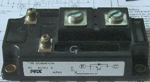
OLTC 2 (Off line Tesla Coil 2) I was given some "bricks" at the Derby Teslathon. ("bricks" are large transistors, IGBT's to be precise.) These ones are Powerex CM300HA-24H. Each one can handle 600A (pulsed) at 1200V. As they will not switch toofast, An OLTC was an ideal coil for them. |
 |
The coil was designed by using my OLTC calculator , from this and available parts I decided on a 6" diameter secondary 20" long wound with 0.2mm wire 2200T. Unfortunatly about 1/3 of the way winding the coil I came accross a tangled peice on the spool, After much tugging etc. I decided to get a new length of wire. Of course I couldnt get a replacement one to match, so I now have a two tone effect. (Actually I quite like it..) |
 |
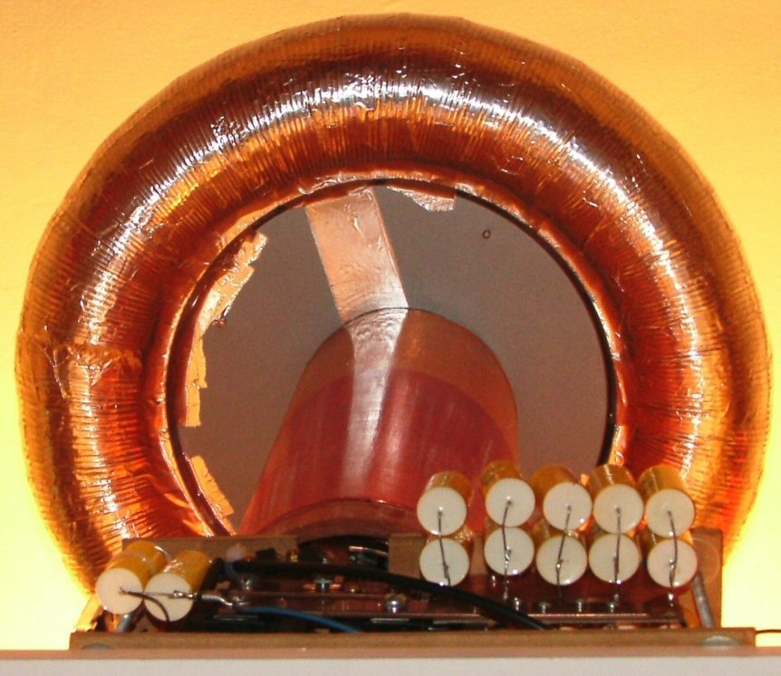
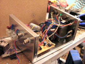
Close up
of the primary coil, caps and IGBT's The Primary is two turns of 20mm x 3mm copper bar, wound around the 6" former. Each turn is insulated from the other by two layers of overhead projector film. The primary caps are placed on double sided PCB so that adjacent ones are wired in opposite directions, this keeps down stray inductance. |
 |
View from
the back. The two IGBT's are nounted onto a 200mm x 150mm x 40mm heat sink , kept cool by two 80mm 12v fans. The rest (8) of the primary capacitors are mounted on this side. |
 |
The power for the OLTC comes from a voltage doubler, 2 x 16A 400V diodes and 4 x 100uF 500V capacitors. The Third diode here is the de-queuing diode for the charging inductor. this give me a total charging voltage of about 950V @ 2KW. |
 |
The IGBT Drive, is designed to run from a single
output of the
AD-OLTC controller . It also allows the circuit to have its own quench timer, and over voltage crobar circuit independant of the AD-OLTC controller. The Circuit is here |
 |
The Base,
wired up and ready to go. |
 |
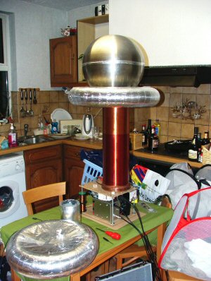
The complete setup, "Made like a brick
OLTC" Inital Results I then went up to the full mains in, The coil worked 8"+ arcs to a ground, but each time I got an arc the overvoltage trip went. After a lot of adding quenching componants etc, I realised my mistake. I'd designed the voltage doubler to give me 550V at 2KW of load, this doubled (resonant charging) with losses would give me 1KV and leave 200V headroom for the 1.2kv bricks. But, at almost no load it was giveing me 640V, so as soon as the resonant charging kicked in the caps got charged to 1000V or more, and the over voltage crowbar fired. So with not enough time to redesign the PSU, I dragged out my variac. I wired it up to give me a lower voltage in, and there was a very loud bang.... A regulator had touched the earthed case, blown holes in the earth track, and blown all of the driver electronics, and one of my precious bricks. OH F^&K !!!! Luckily, I had a friend with a spare brick, So I replaced all of the driver and the blown brick, and started again, checking VERY carefully. SPARKS!!! 16" at around 100Hz with no problem at all.. The only down side is the Variac, (OLTC's shouldn't need power transformers) but I don't think it counts as a supply transformer as its a STEP-DOWN transformer... |
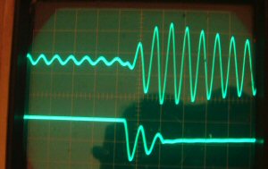 |
A picture of the secondary (to air) voltage against the primary capacitance voltage. The tuning is about right. I do seam to have no sharp tuning point, but maybe I need to use smaller caps to hit the resonant peak, At present I'm changing the capacitance by adding or removing 0.47uF's or two in series to make a 0.235uF, The coupling is about right with ring-up in 2 Cycles. |
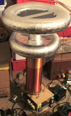 |
In an attempt to get more primary capacitance I made a couple of toroids from ducting, pie tins, frisbys etc. Top one is 4"x20" and the bottom one is 4"x18" This gave me about 1.5uf more than the sphere did on its own, but I've still got disapointing sparks. At max 2' this is limited by spikes shutting down my over voltage protection cct, especially when you get a fat arc to earth. |
  |
In an
attempt to stop arcs from tripping the overvoltage trip I have enclosed
all of the driver electronics in an ALU box. The mains in goes via a 0.9uF filter cap, and the fans and relay are decoupled by 0.1uF on entry. Inductive filters may be added later too. |
 |
Ikea have started to stock large
stainless steel salad bowls again, so I bought two of the 13" ones to give
me a rather snazzy looking sphere. This has the same capacitance as
the two ducting toroids above. I think some of the problem is my rather lousy earth in my attic, I dont think its up to 1.5KW of RF being pumped through it!! Undeterred I have replaced the 6A trip with a 10A one, and I'm now waiting for a trial with a decent earth. Probably at the Cambridge Teslathon.
Ikea have started to stock large
stainless steel salad bowls again, so I bought two of the 13" ones to give
me a rather snazzy looking sphere. This has the same capacitance as
the two ducting toroids above.
|
 |
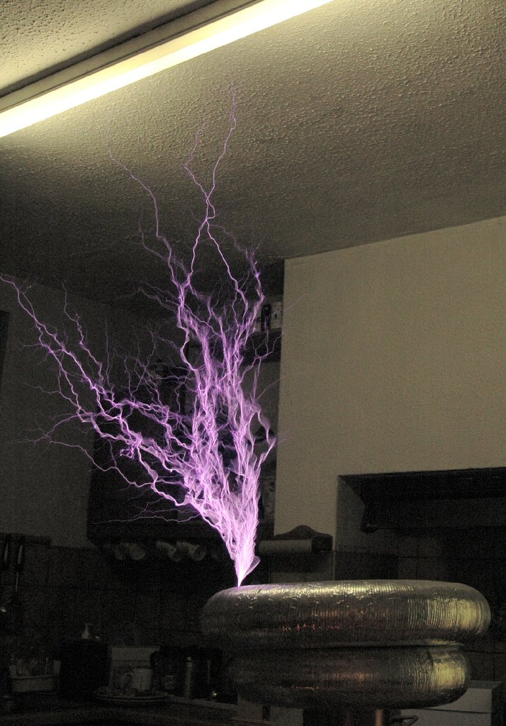
As the February Gaussfest was coming up, I decided to have another go at getting more out of the coil. I managed to persuade my wife to let me use the kitchen table as a test bed, giving me much more room than the attic. I re-wired the screening on the driver case to use 0V rather than mains or secondary earth and re did the screened cables to the 0V pickup from the bricks, leaving much less unshielded than before. I also found that if I lowered the whole of the top platform on the studding, I could lower the secondary without moving the primary this gave me the ability to increase the primary-secondary coupling. After a few minutes of tuning, I wound it up to about 800V at about 200BPS and got a power arc to the fluorescent light in the kitchen, 28" above the coil, without blowing the over voltage trip. Excelent! , but t his does rather limit my testing any further. ( and my wife wants the kitchen table back. 😉 ) So next test at the Gaussfest. |
 |
OLTC 2 (Off line Tesla Coil 2) continued The Coil ran Ok at the Gaussfest, but still not much improvement on 2.5'. I did manage to run at full power 2.4KW (10A at 240V) which proved the electronics can stand abuse. So after the Gaussfest I started to look at ways of
increasing the bang energy. This pretty much came down to lowering the
primary inpedance. |
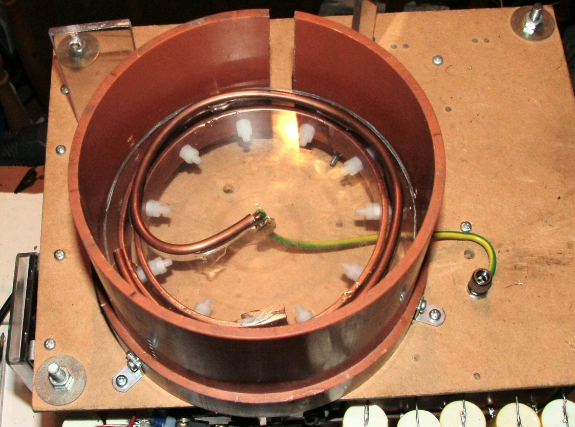 |
I also raised the primary up by about 12mm so the base of the primary is now level with the base of the secondary. This should give me more control over the coupling. The Inner of the secondary is drilled so I can adjust the exact height of the secondary RWT the primary. I have also added a strike rail inside the secondary in an attempt to catch any internal arcs before they contact the primary and upset my bricks. This is a spiral of 5mm copper pipe on a disk of 4mm acrylic placed over the primary coil. |
 |
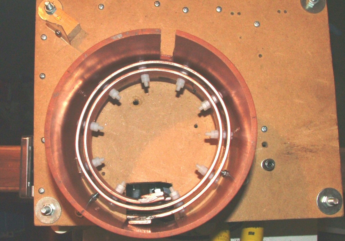
A
Picture of the OLTC2 from below, just because I like the picture and
to show that I now have 8.46uF of primary capacitance. (18 x 0.47uF = 8 x
0.47uF inside + 10 x 0.47uF outside =
8.46uF) which
gives 4.23 Joules per bang at 1KV |
 |
The OLTCII ran quite well, but I had all sorts of problems, Mostly due to interferance when arcing to earth tripping the over voltage trip. After a lot of rebuilding and screening, I decided to replace the controller cables with an optic fibre. The improvement was huge, I could arc to earth with no problems. But of course that wasn't the end of the problems. I now had a strange "PING" sound at high powers, and this did blow the HV trip Eventually I pinned this down to being an arc forming on the inside of the secondary. Again after a lot of playing, I found that this was racing sparks. Lowering the coupling sorted out this problem ans I had another session in the testing room (the kitchen). 45" Sparks !!!! |