The Story of Electricity III
Published on Nov 19, 2012
Shock and Awe – The Story of Electricity. Revelations and Revolutions: How understanding the secret of electrical superconductivity could transform the world.

The Story of Electricity III
Published on Nov 19, 2012
Shock and Awe – The Story of Electricity. Revelations and Revolutions: How understanding the secret of electrical superconductivity could transform the world.
The Story Of Electricity II
Shock and Awe – The Story of Electricity. The Age of Invention: Jim Al-Khalili reveals how scientists and engineers unlocked the nature of electricity in an extraordinary century of innovation and invention.
The Story of Electricity Part 1
Published on Nov 19, 2012
Shock and Awe – The Story of Electricity. Spark: Jim Al-Khalili tells how the first ‘natural philosophers’ began to unlock electricity’s mysteries, studying its curious link to life and building instruments to create it
by Paul E. Schoen of P S Technology, Inc.
There is some more information [regarding the resistance of a human body] at http://van.physics.uiuc.edu/qa/listing.php?id=6793 , where it states that the external human body resistance is about 1k to 100k Ohms, and the internal resistance is 300 to 1000 ohms. Only a thin layer of dry skin separates the internal resistance from an external object.
The human body capacitance to a far ground is 100-200 pF, which is really a minimum value. This correlates to an impedance of about 13 megohms at 60 Hz, which corresponds to a minimum of 9 uA at 120 VAC to ground. This is enough to be sensed and used for capacitively operated light dimmers.
Here is a way to measure your body capacitance: http://web.mit.edu/Edgerton/www/Capacitance.html
The inside of your body can be considered a conductor, and thus if you place your hand flat on a metal plate, you will form a capacitor with an area of perhaps 15 square inches, with a thin (maybe 0.005”) insulating layer of dry skin, which will form a capacitor much higher in value than the 200 pF stated above. According to a formula in http://www.sayedsaad.com/fundmental/11_Capacitance.htm , this would be C = 0.2249 * k * A / d = 1350 pF, (assuming k for skin is 2, about like dry paper). This will be an impedance of about 2 megohms , and current of 60 uA. This is still below the normal threshold of sensation, and still far below the usual safe current levels of 1 to 5 mA.
The actual thickness of the epidermis (per http://dermatology.about.com/cs/skinanatomy/a/anatomy.htm ) varies from 0.05 mm (0.002”) for eyelids to 1.5 mm (0.06”) for palms and soles, but the actual outer layer of the epidermis that is a good insulator is composed of flat, dead cells, which is much thinner. So the capacitance could be much higher than the quick estimate above.
Probably the main reason for electrical current to reach levels high enough for electrocution to occur (6 to 200 mA for 3 seconds, according to http://www.codecheck.com/ecution.htm ), is when skin becomes sweaty or otherwise loses its dry protective layer, which quickly exposes the underlying 1000 ohms or less, which will conduct 120 mA at 120 VAC.
There are safe ways to measure the body’s resistance and capacitance using realistic higher voltages, skin conditions, and contact surfaces, but I’m not going to suggest anyone try it. Suffice it to say that ohmmeter readings are misleading, and any carelessness around any kind of voltage source can be dangerous.
For very high voltages, there are standard minimum distances that must be maintained between a worker and an energized line: http://www.dir.ca.gov/oshsb/rubberglove.html . I found this on a search for rubber glove testing.
The field intensity near high voltage lines is so great that it might be fatal to touch them even if you were suspended in free air. You may notice that birds can sit on lower voltage transmission lines which are 5kV to 50 kV or so, but not on 200kV+ lines.
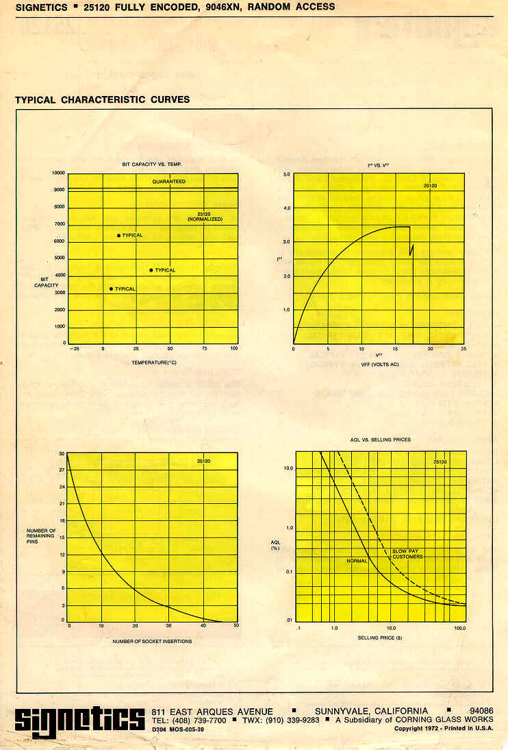
Signetics – Fully Encoded 9046 x N, Random Access Write – Only – Memory
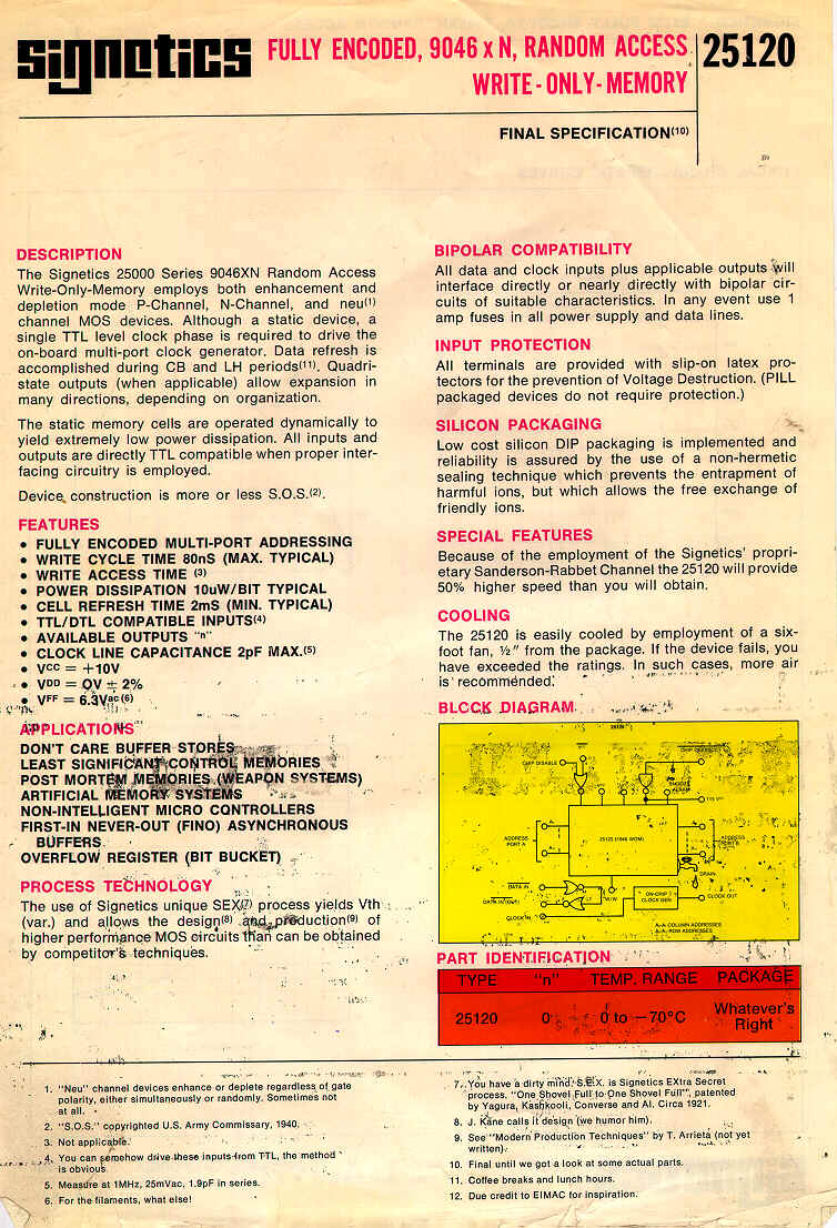
Released in the Early 70’s For some reason the IC didn’t take off. Although I can think of a number of machines that must have used these devices.
Edit /etc/network/interfaces
Change
[code]iface eth0 inet dhcp
to
iface eth0 inet static
and below enter
address 192.168.100.1
netmask 255.255.255.0
network 192.168.100.0
broadcast 192.168.100.255
gateway 192.168.100.254
So I bought a Minimus32 Development board from [shortlink url=”http://www.modtraders.co.uk/minimus-32-avr-usb-development-board.html” title=”Mod Traders”]
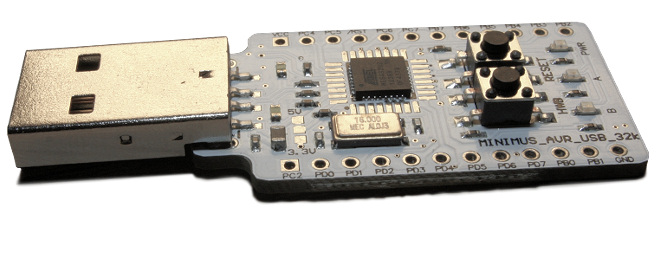
Couple of reasons for the purchase, Its was cheap, and it had a small processor and USB support out of the box.
OK, 1 and 2 are true, 3 is a little more complex.
After trawling the internet All I found was out of date information, information on the original Minimus board, or information using an old version of Atmels IDE. Having struggled in the past with old IDE’s I decided to use the newest one and brave it out.
So, For Windows…
You can download Atmel’s latest IDE free from here [shortlink url=”http://www.atmel.com/microsite/atmel_studio6/” title=”http://www.atmel.com/microsite/atmel_studio6/”] It is a Visual Studio based IDE and looks pretty good. Unfortunately there is no support for the bootloader contained in the minimus32 board.
So to get a hex image onto the Minimus 32 you need Flip downloadable for free here [shortlink url=”http://tinyurl.com/7jqeg3l” title=”http://www.atmel.com/tools/FLIP.aspx”]
Braving the new environment I cut and pasted a demo code sample (blink )
[code]#include <avr/io.h>
#define F_CPU 16.000E6
#include <util/delay.h>
#include <avr/wdt.h>
void init_ports(void)
{
PORTB = 0b00000000;
DDRB = 0b00000000;
PORTC = 0b00000000;
DDRC = 0b00000000;
PORTD = 0b00000000;
DDRD = 0b01100000; // Set LEDs as output
}
int main(void)
{
MCUSR &= ~(1 << WDRF);
wdt_disable();
init_ports();
while(1)
{
if (PIND & 0b10000000) {
PORTD = PORTD & ~0b01000000;
PORTD = PORTD | 0b00100000;
_delay_ms(200);
PORTD = PORTD & ~0b00100000;
PORTD = PORTD | 0b01000000;
_delay_ms(200);
} else {
PORTD = PORTD | 0b01100000;
}
}
}
I set the uP to ATMEGA32U2 hit build and It compiled first time.
Went into Flip, loaded the .hex file and sent it to the Minmus32. After a little playing with the buttons it ran.
(Tip: to put the Minimus into “Load” mode you need to press RESET, press HWB, release RESET and release HWB, just roll your finger over the buttons)
So a USB example.
I found that you can get the latest version of the LUFA libraries from here [shortlink url=”http://tinyurl.com/mx8flmo” title=”http://gallery.atmel.com/Products/Details/47ba24a4-d17b-4fed-b244-f5998b3d789d”] and the are already formatted for Studio 6
Loaded the Libraries and tried the demo project for USB to RS232
It compiled, but wouldn’t run.
Cutting a long story short there were a number of things wrong. The Processor speed was incorrect, the target board wasn’t set correctly and the LUFA libraries didn’t contain the code specific to the Minimus32 Board.
So. to fix these.
In Atmel Studio 6, Goto Project->Toolchain -> AVR/GNU C Compiler -> Symbols
Ensure they look like this
[code] F_CPU=16000000UL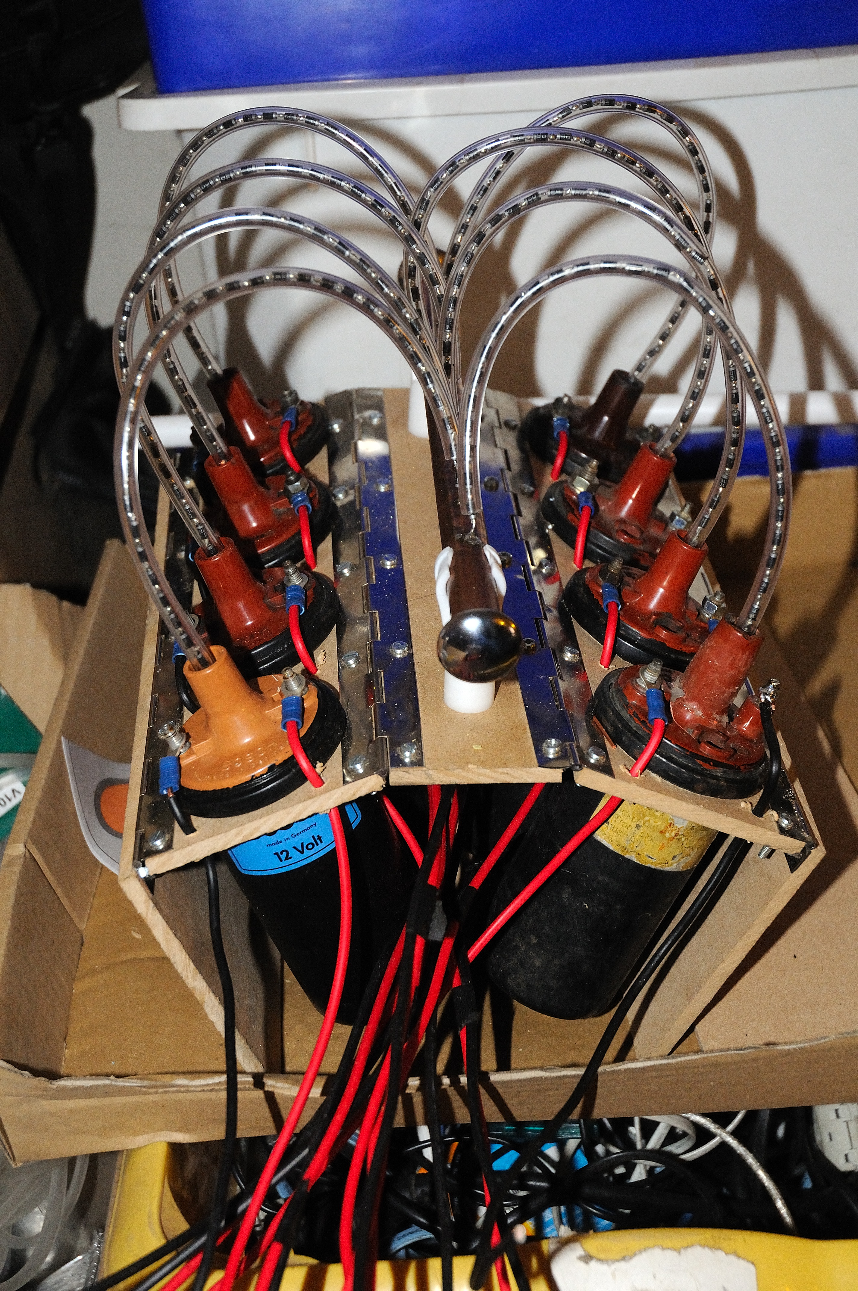 The V8 Ignition coils
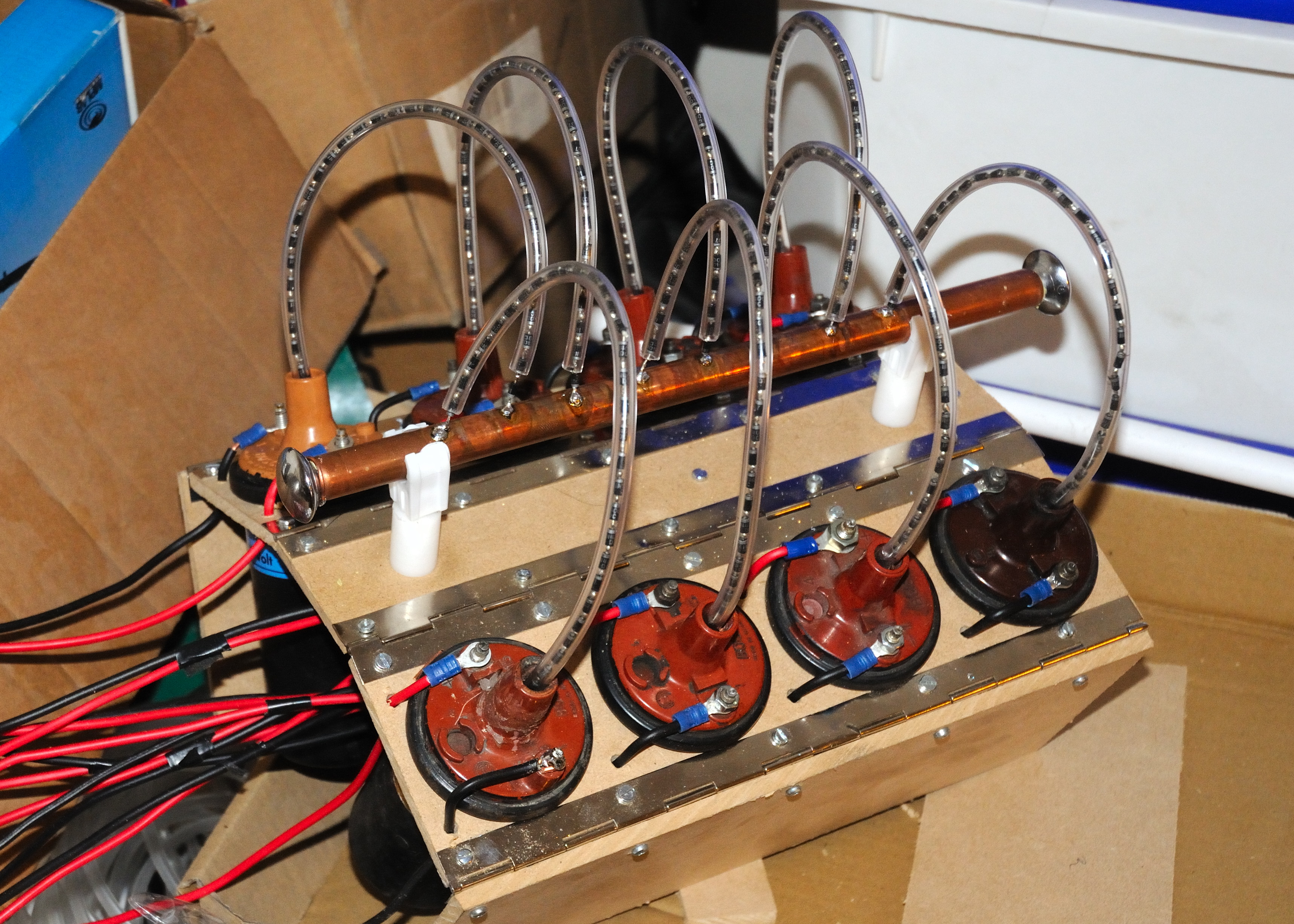 A 30 Kv power supply using 8 car ignition coils. The output of the coils are rectified with strings of 40 x 1n4007 diodes.
Each ignition coil, run flat out, draws around 5A at 12V so in theory the output should be around 300-350W drawing around 40A from the 12V supply.
The advantage of this drive is that there is no mains to back any fault, so it does make using the supply (slightly) safer than a mains powered unit.
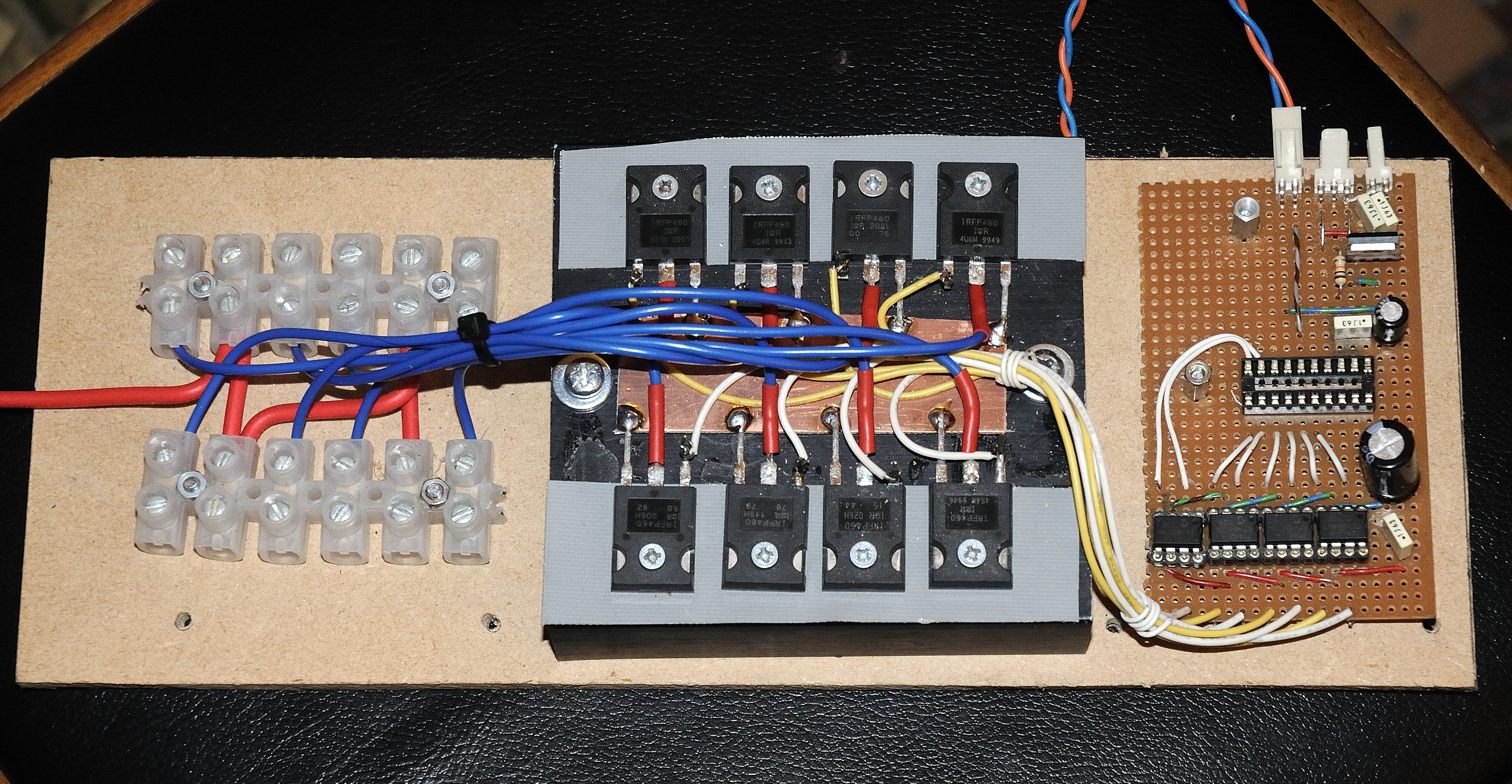
The ECU (Engine Control Unit)
The heart of the power supply is the ECU. The ECU gives some control of the output power of the system. The power is controlled by a variable resistor which controls the average power to the coils.
By arranging that no coils fire at exactly the same time as any of the others, the peak current draw from the batteries is limited, this allows smaller batteries to be used at lower powers. It also smooths the output so a smaller HV smoothing capacitor may be used. It effectively gives an 8 phase rectified HV supply.
To implement this there is a PIC18f14K50 controlling the timings of the 8 coils and taking control from a variable resistor. The PIC ensures that the on time of each coil is set to a maximum value ( 2.5mS for now can be as high as 3.5mS) so the coil will not be run into total saturation. It also spreads the pulses out over the 8 coils to prevent multiple coils turning on at the same time (except approaching full power where this is unavoidable.)
We have POWER!!! First test at full voltage 24v (2 x 12v SLA) into a jacobs ladder. Added 0.1uF caps across each of the coils to limit voltage rise when turned off. This is a much bigger problem at 24V than 12V. No clues at actual power. Well over 10A. My meter only goes up to 10A, and the fuse blows at 12A, I need a larger ammeter, and a new fuse. Continued in Strand on Tesla Coil
[shortlink url=”http://tinyurl.com/msd4o8v” title=”Continued From V8 Tesla Engine”]
After playing with the V8 Tesla engine I realised that I could build a stand on tesla coil. The lack of mains power could make this “fairly” safe.
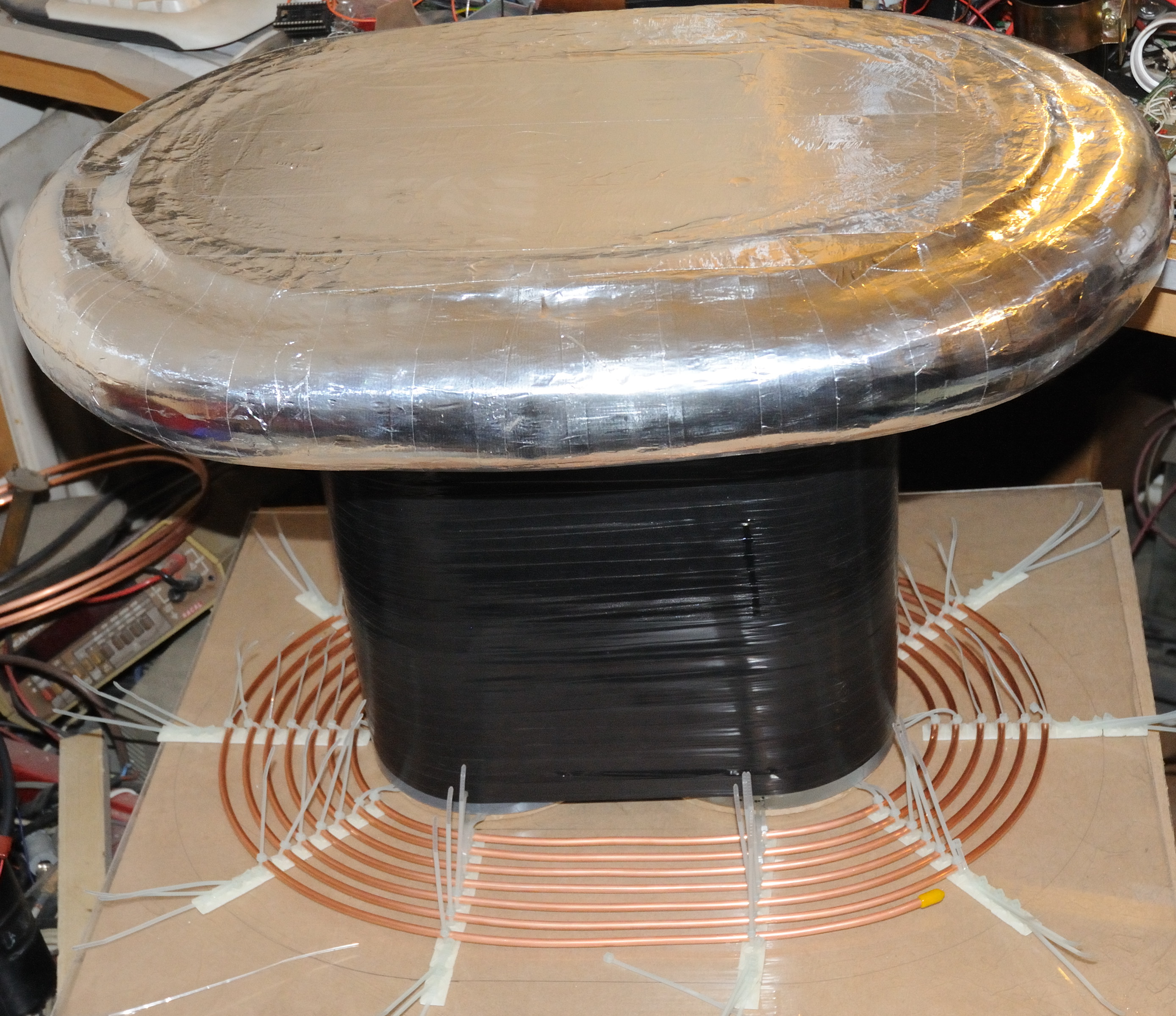
So I started with a topload that was big enough and strong enough to stand on. I started with a pair of 110mm PVC tubes and joined them together. The thought was to make an oval tesla coil (big mistake).
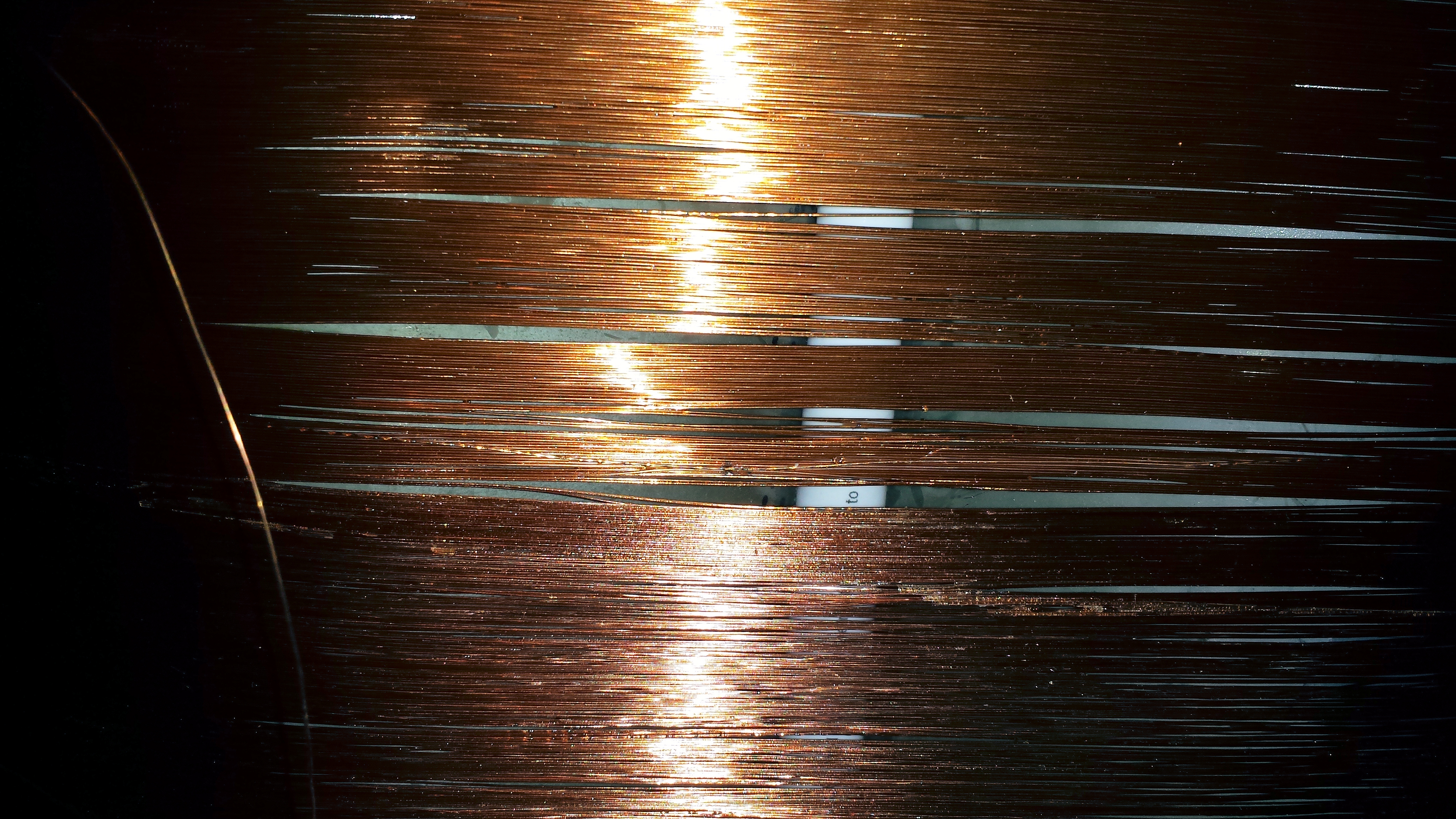
After winding the secondary, by hand (1000T of 0.33mm wire ) on to the former I started to realise that there was a problem, the wire stretched slightly and started to sag between the two tubes. To give the wire some support I wound PVC tape around the coils as I completed them. This was partially successful, but as I had nothing to loose so I continued.
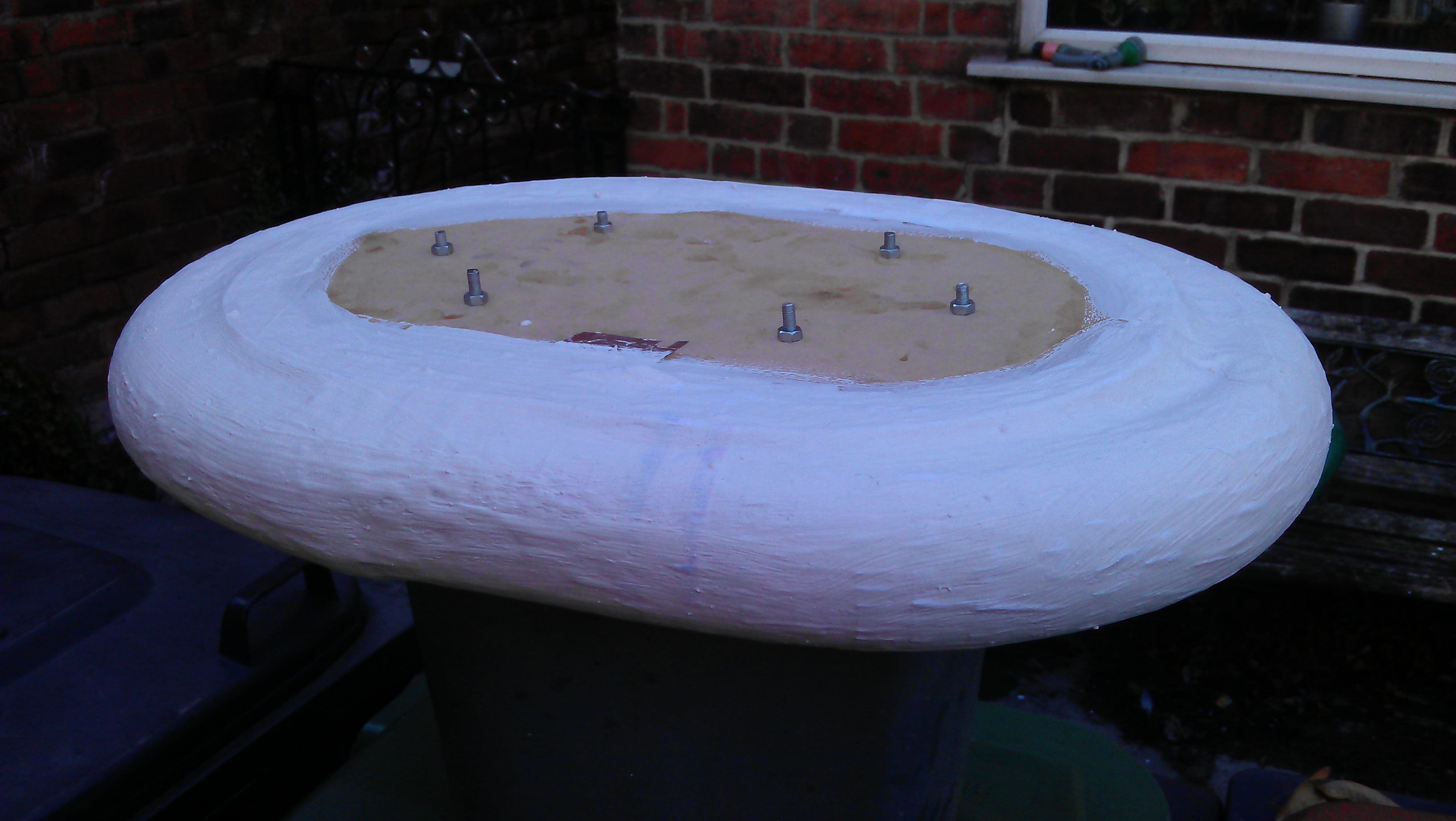
The Topload needed to be strong enough to
stand on too and smooth and an oval.
So I started with an MDF former of 3 oval sheets spaced to a total height of 2.5″, and an external wrap of pipe lagging to give the external shape.
Over this I added paper mache and then a covering of plaster and PVA glue to give it strength. This last layer could be sanded to smooth out the edges.
 The Primary, I quickly roughed out from 50′ of 5mm break pipe held in an oval spiral with cable ties and adhesive.
The output from the V8 tesla engine is fed into a primary cap and an crude sparkgap.
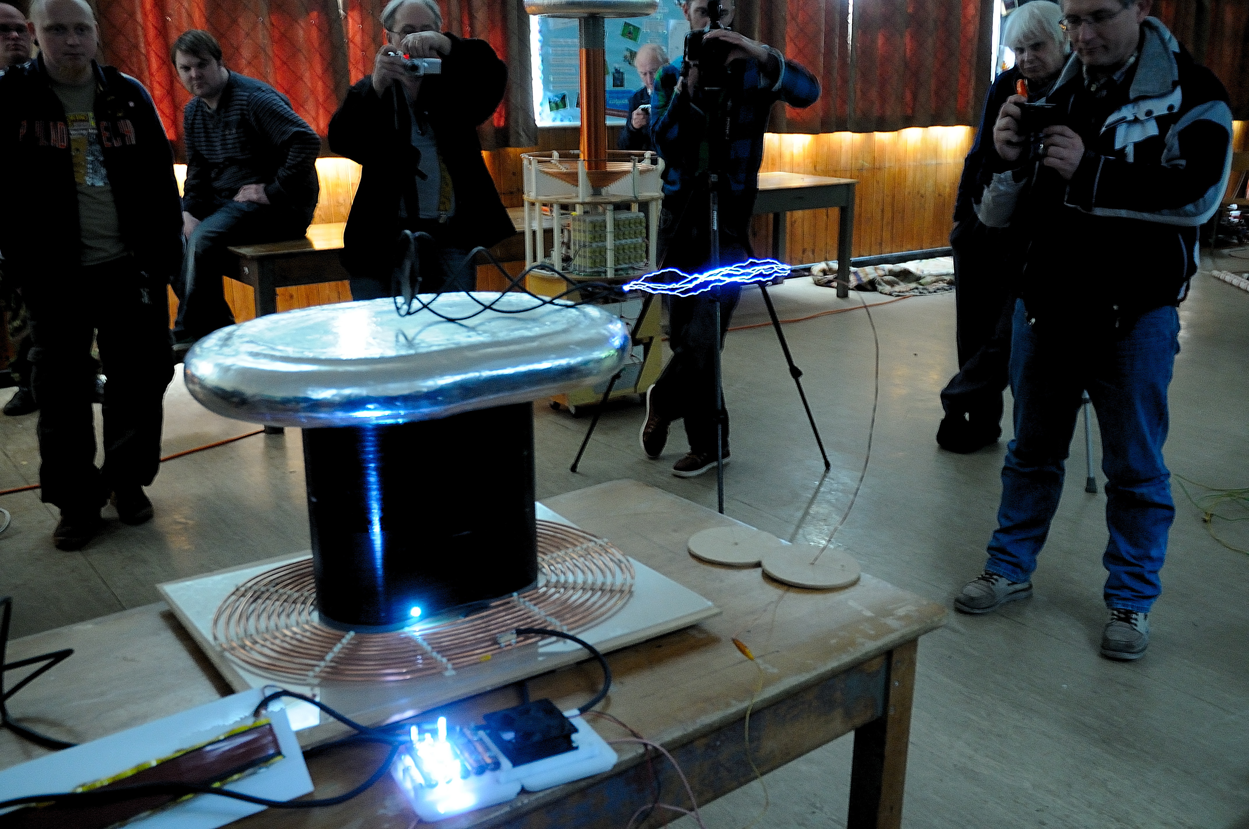
Here is the coil working at the Nottingham Gaussfest.
Note that the problems with the secondary coil are starting to show with a breakout at the bottom.
But it was worth having a go at standing out the coil. After a while I found that the tuning point changed only a single turn when I was standing on the coil.
Below is a video of the first run with me on top.
So I realised that the secondary needed to be re-built The pictures below show the damage.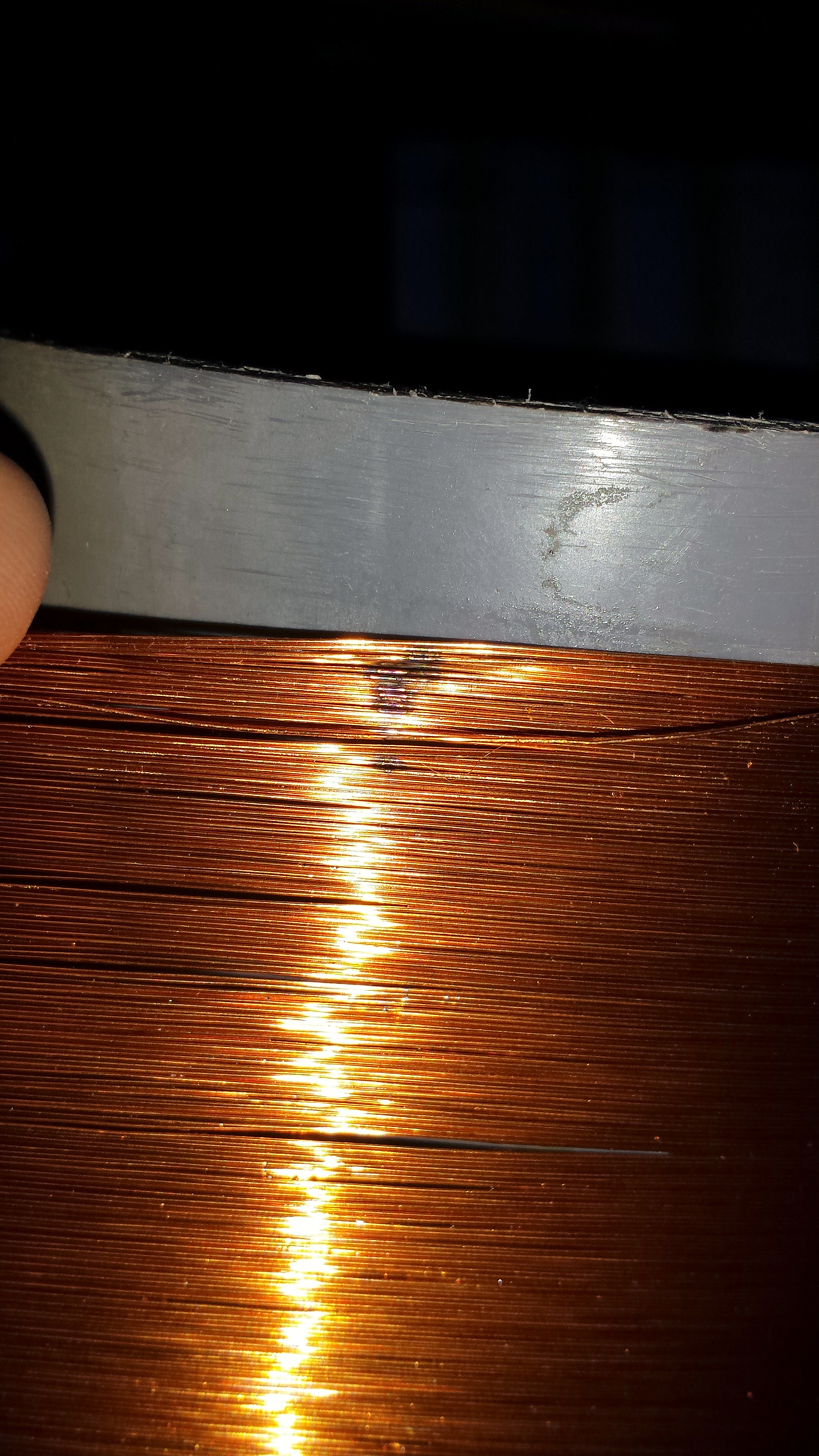
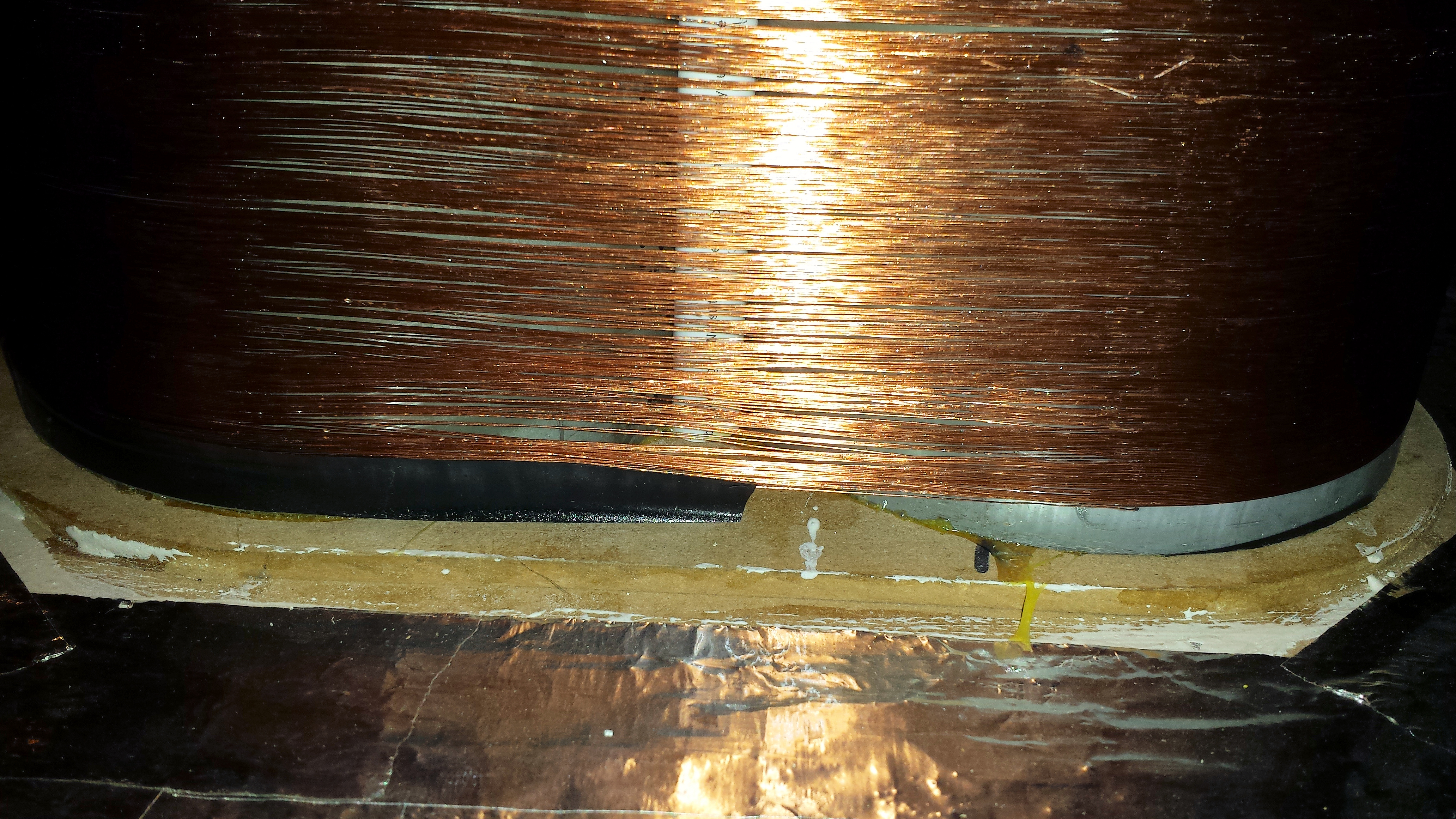
So the rebuild begins
This time I’ve packed out the space with some cardboard in the void between the PVC pipes and sheets under the coil bridging the two pipes. The cardboard is held in place with many layers of adhesive craft paper that was varnished before the wire was wound on.
The finished article looks a load better then the old one, but there is still some minor ‘droopage’ between turns. So the coil was heavily varnished after winding.
Hopefully it will not suffer the same breakouts as the old.
Also I decided to clean and re-mount the sparkgap the old copper pipe gaps were a little? corroded.
The Sparkgap is mounted on to a channelled acrlyic chamber that allows a high volume fan to blow air over the gaps for cooling and more importantly spark quenching.
Better results from the new coil
First light of a Tesla Coil tuner.
 So I needed to get a better Tesla coil Tuner. I have been using this NE555 pinger for 10+ years.
Always said I’d put it in a box.. Never happened…
With some of the tuning problems I’ve had recently I needed a better solution.
So..
PIC powered USB controlled Tesla Coil Tuner using AD9850 DDS Frequency Synthesis.
Built on a PIC low pin count, USB development board (hence redundant RS232 connector)
Direct connection to the Primary Coil with current measuring.
Three ways of measuring.
Primary and cap on its own(Secondary removed)
Secondary on its own (driven by primary with no Primary cap)
Primary Cap and Secondary (across spark gap) – Should see both current dips.
First plot of a small Secondary coil, using VB to drive the USB.
Plots at ~15 seconds for 1000 points (e.g will scan from 500Khz to 1.5Mhz in 1khz steps in ~15 seconds.)
Range 50Khz to 4Mhz (with some droop at each end)
I’m having some issues getting a plot with just a primary coil, not sure why at the moment. Also my driver (tc428) is damaged, its not driving correctly to ground. Which may be causing me some issues. But not bad for a first go.
More developments
Added an Ariel input (B)
Improved the display, and removed a whole load of noise on the traces.
Also, added the ability to take snapshots of the traces (pale colours) so you can see any change from scan to scan
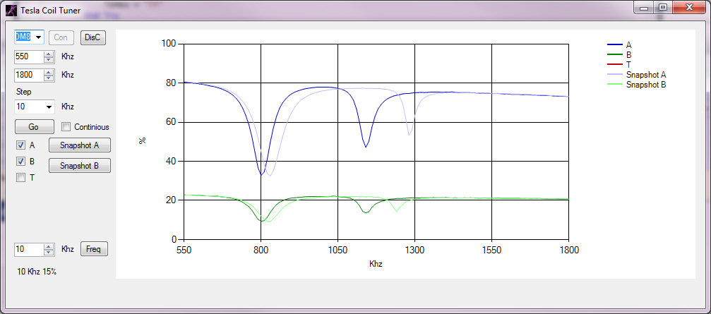
This shows a current scan in Dark blue, with a snapshot in light blue and the Ariel input in dark green with a light green snapshot. The current scan was done with my hand near the topload hence the lower resonant frequencies.
This clearly shows the primary (C & L) as a large dip on the left and the secondary / topload as the smaller dip on the right. I’m feeding the primary coil and primary cap in parallel as this gives the best indication of the current change in the primary. For some reason driving the coil with Cpri in series shows a lumped resonance (or doesn’t show the primary resonance up at all)