 |
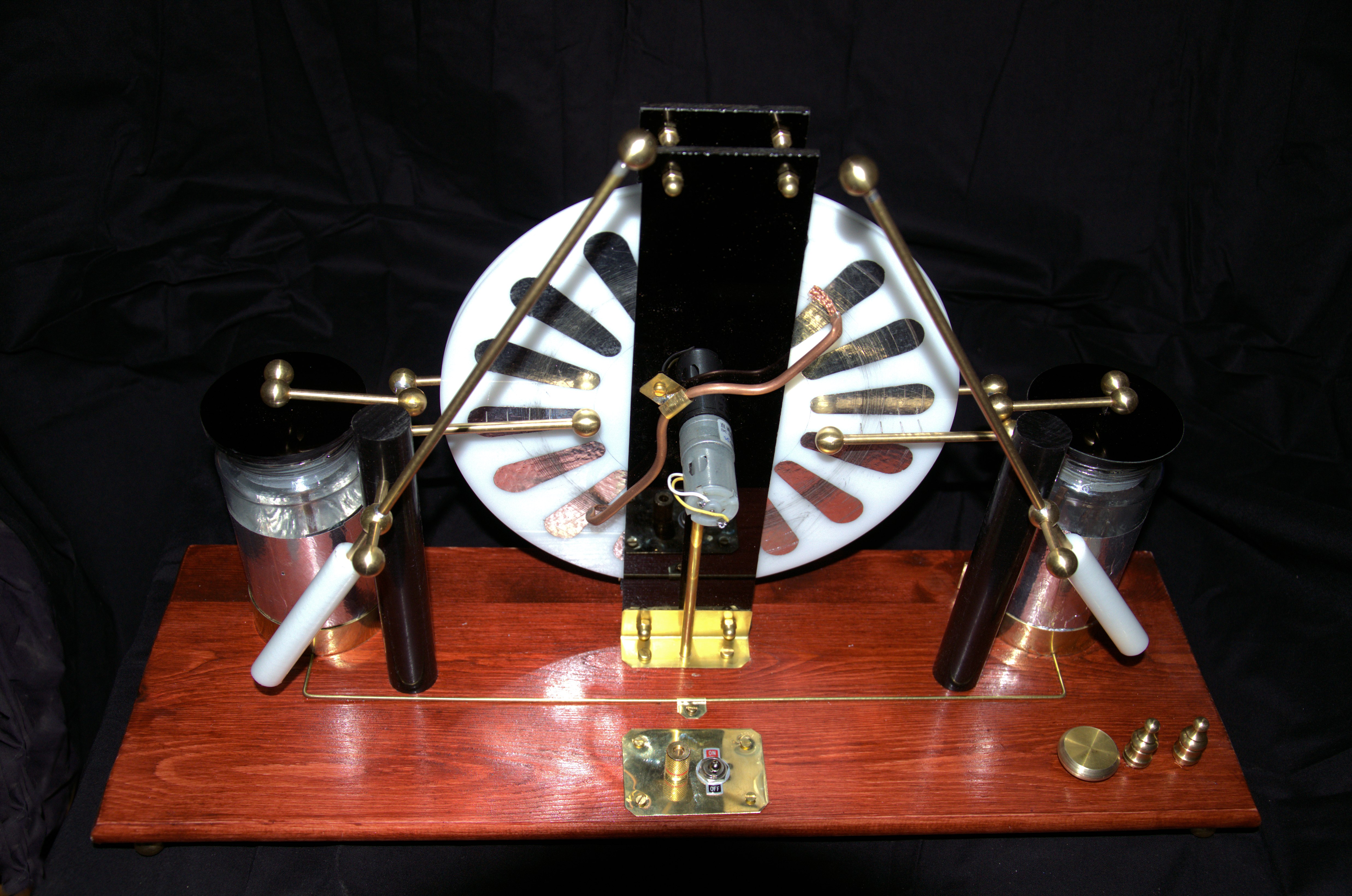
A Classic wimshurst electrostatic machine, Two leyden jars, adjustable terminals. with a range of screw in terminals. A slight deviation from the classic wimshurst is that the two discs are directly driven by geared motors. The power is taken from a set of 4 AA cells mounted under the wooden base. |
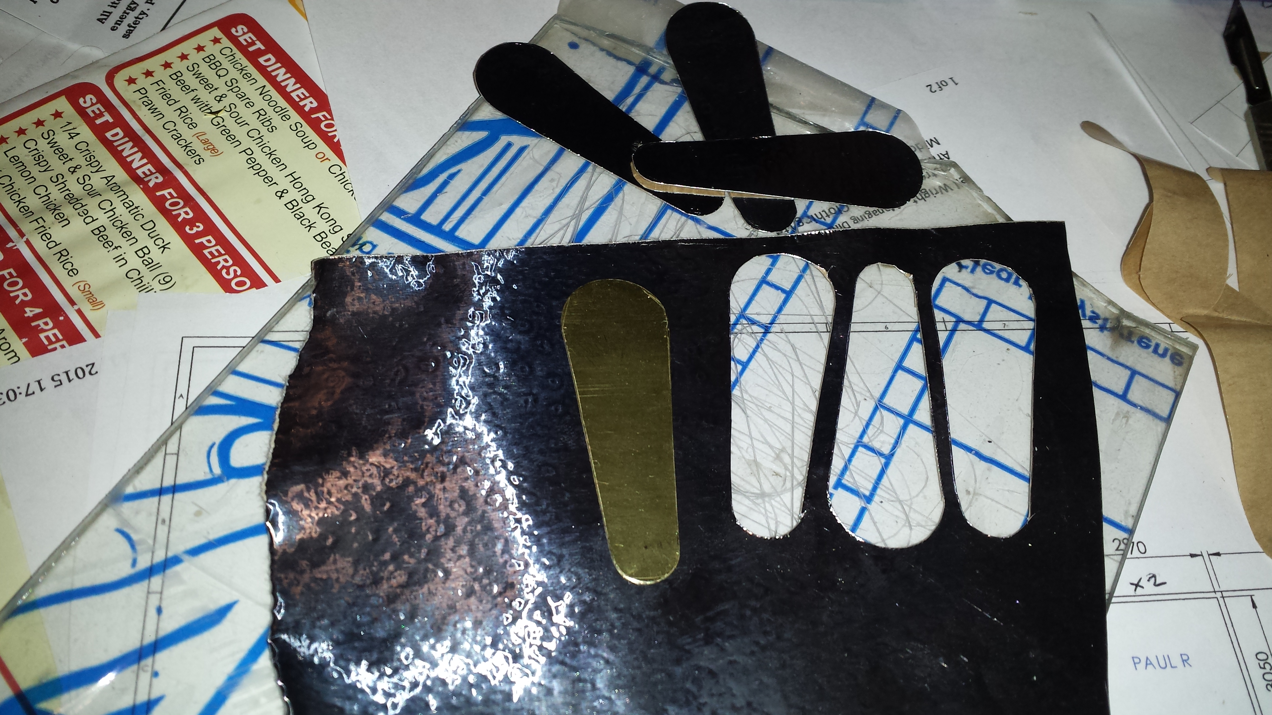 |
The sectors for the wimshurst discs are cut from adhesive aluminium tape used for fireproofing. A pattern was cut from a spare peice of metal and this was used as a template. the Aluminium was cut using a scalpel. |
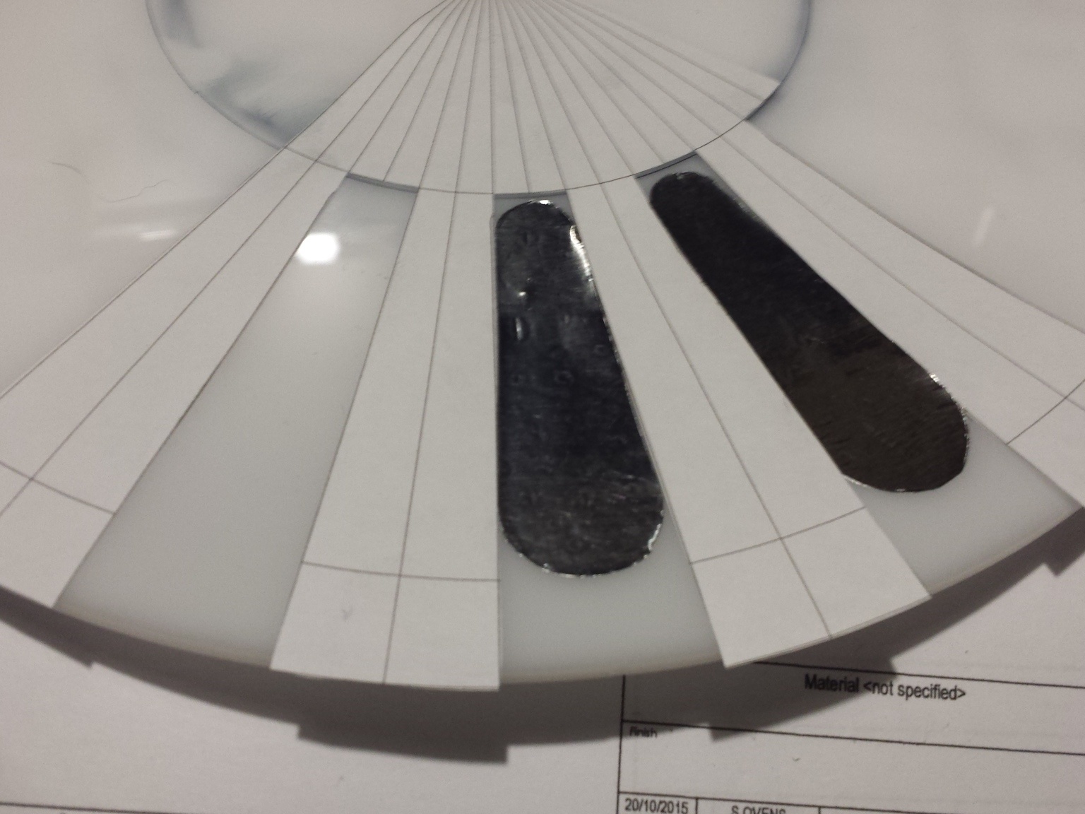 |
I printed out a template to allow the sectors to be evenly placed on to the disk and to ensure they are all at the right distance from the centre. I also drew a circle to make the bottom of each sector with a white board pen. |
 |
A completed disk, One word of warning when you mark out the disks with a white board pen, ensure you haven picked up a sharpie. It takes some getting off. |
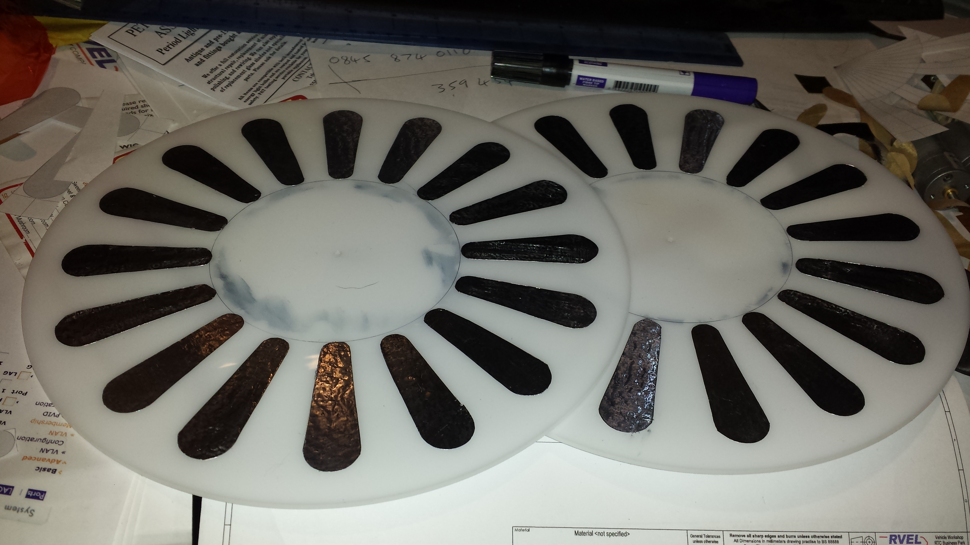 |
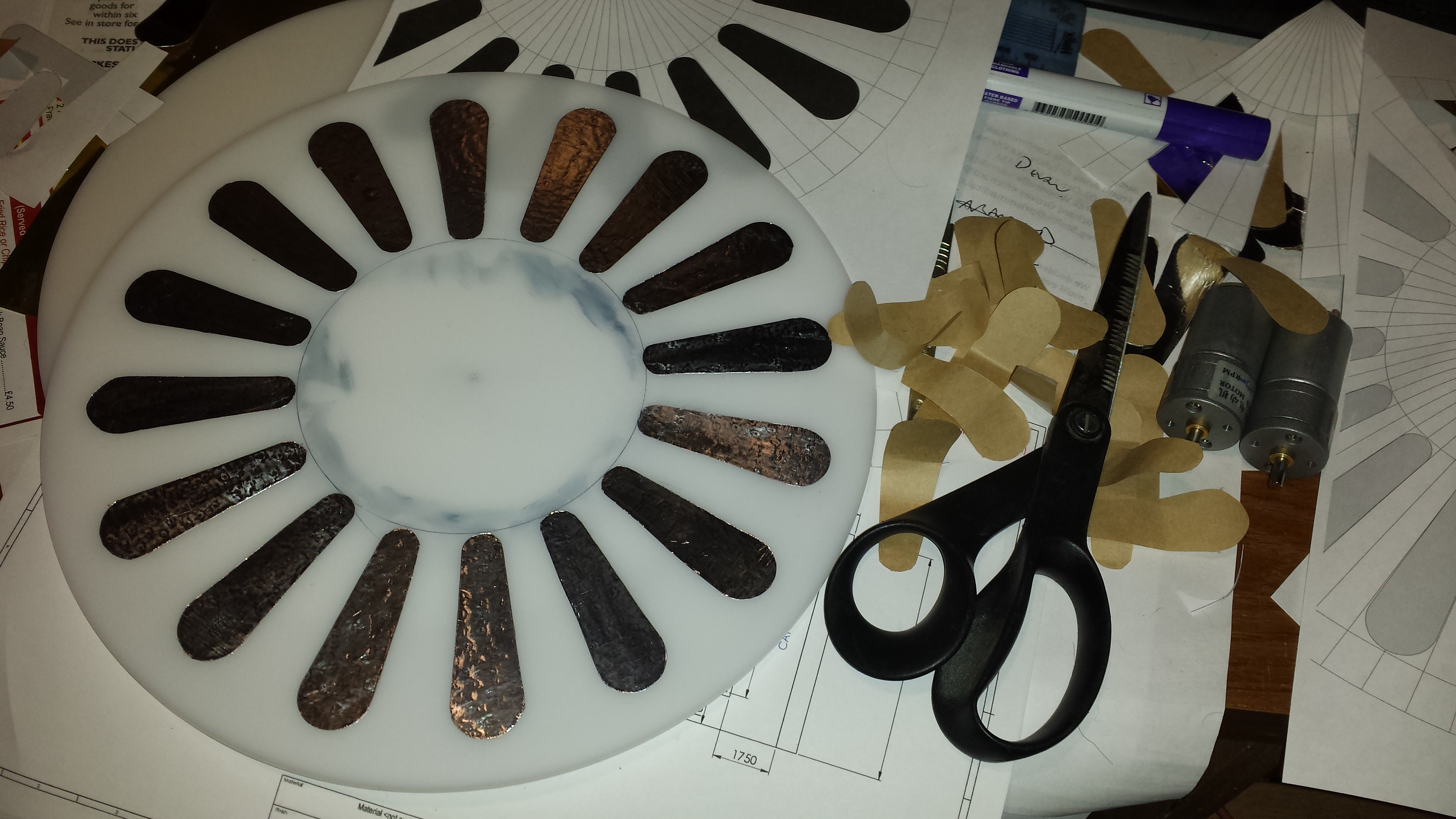
The two completed disks both 250mm in diameter. |
 |
As the discs are driven directly the strength of the center boss is vital to ensure the disks run true. After a number of attempts at machining one myself and not getting anywhere near the accuracy required. I found a site that sold brass replacement meccano parts. IM4 screws This allows the disks to be set really close together |
 |
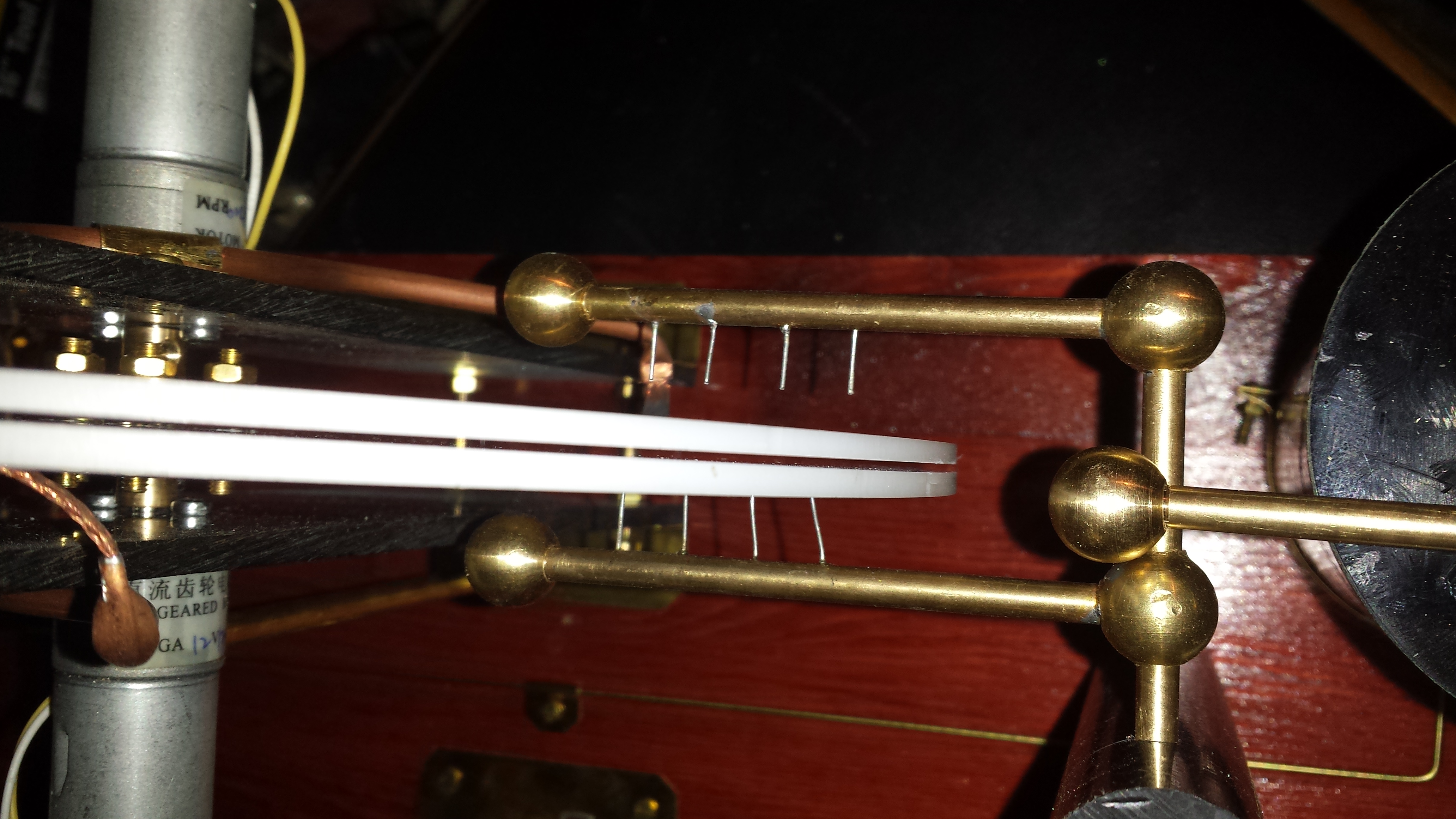
The motors are mounted on two pieces of black acrylic and the wires partially hidden by a 6mm brass tube that goes to the bottom of the base board. Each motor has an integral 4:1 gearbox.
There are two neutralising bars that run past the motor these were made from two pieces of copper brake pipe. I used copper so I could easily make the bend around the motor. The brushes are made from the copper braid taken from a piece of coaxial cable |
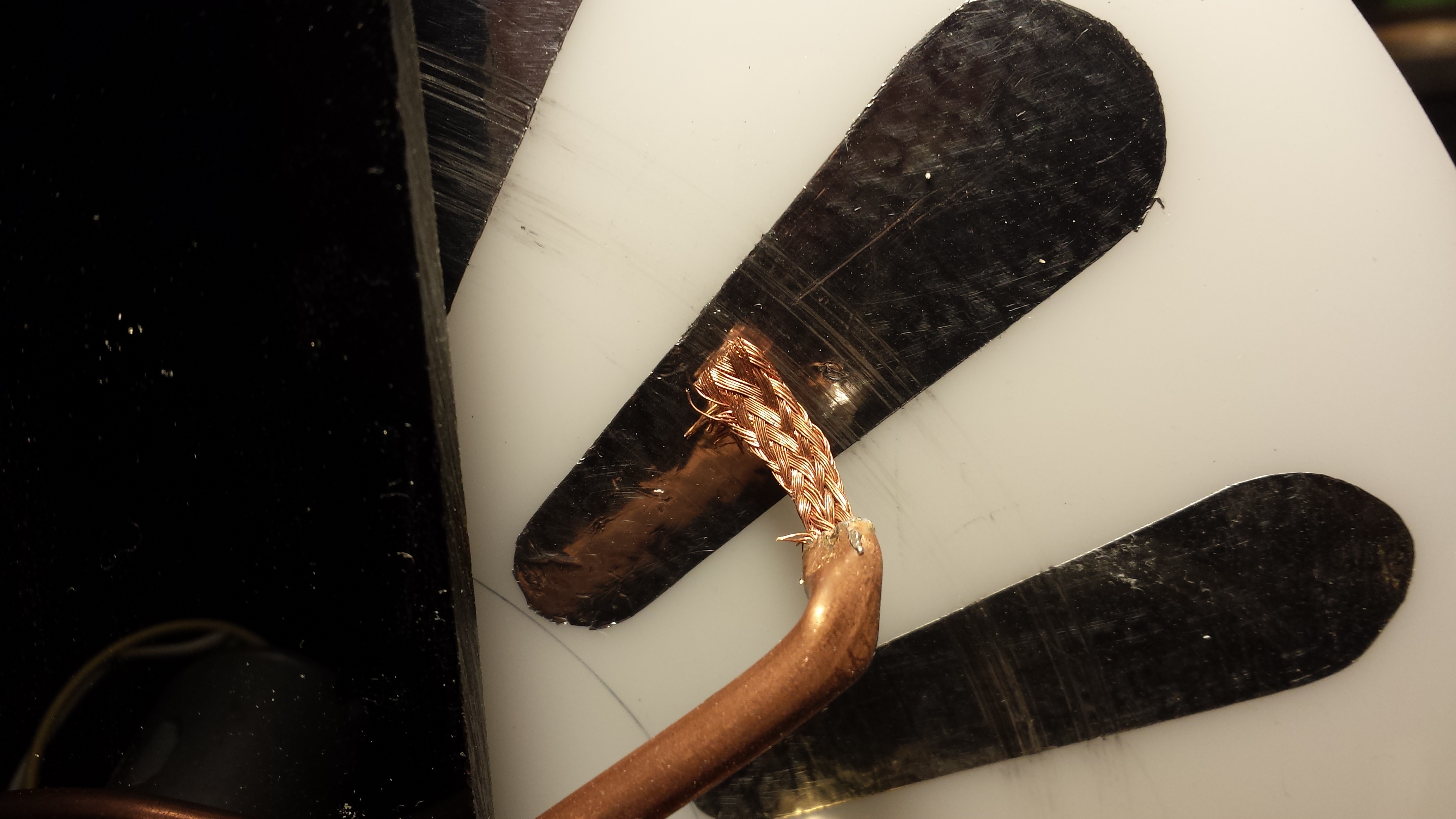 |
It also allows the copper braid to be soldered into the holes in the ends of the tubes. The tube can then be easily bent to adjust the pressure on the brushes. |
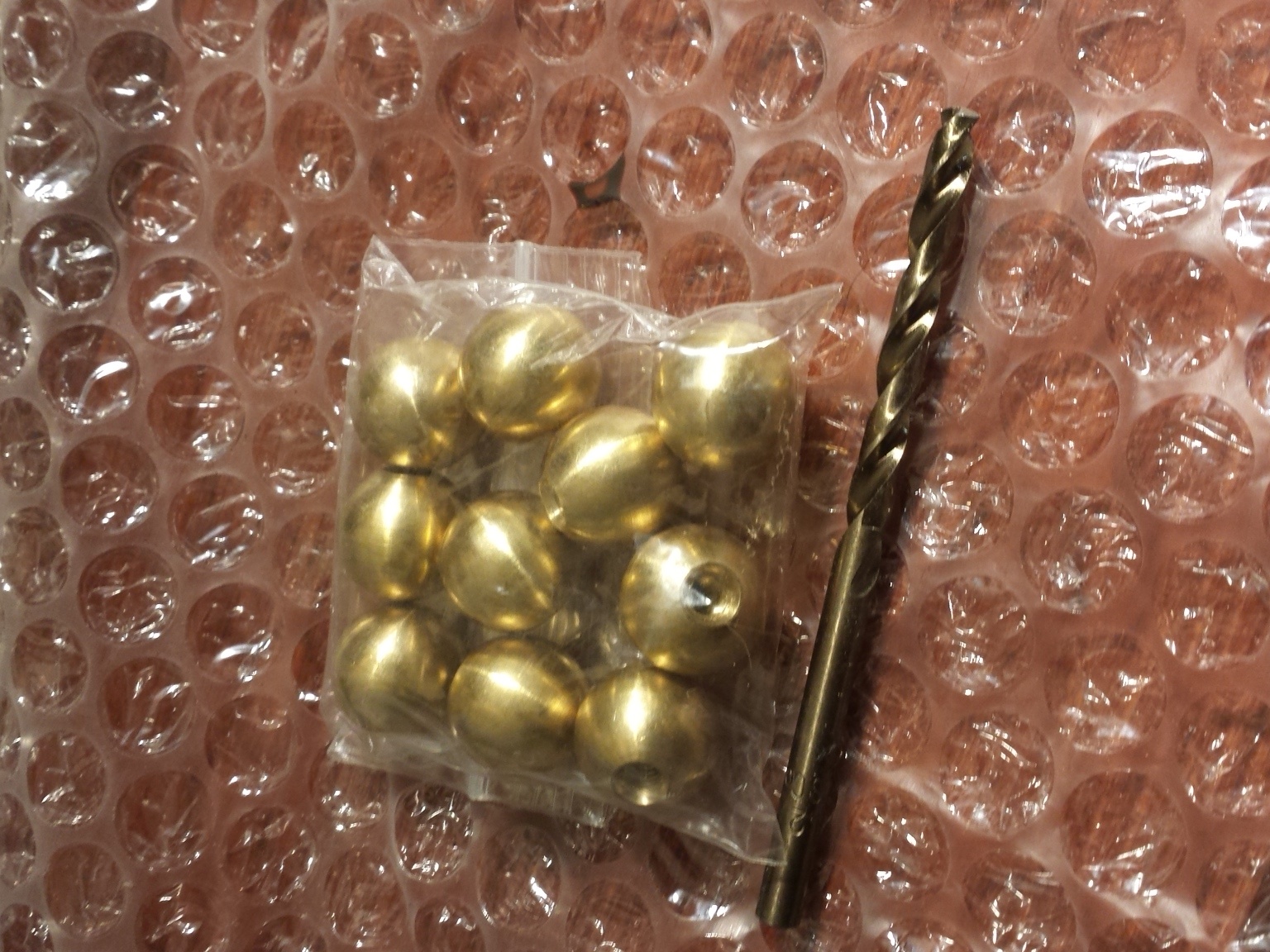 |
As I started to plan and build the wimshurst I realised that the main components needed to be terminated or joined with brass balls, the more I needed, this caused me to make a number of orders to the only place I could find reasonably priced brass components Peter Willetts Associates (trust me to try and make something out of brass at t a time when brass prices were really high). The only issue with these balls (and other brass parts) is they come with either a 4mm or 10mm thread. |
 |
All of the major parts were connected by 5mm brass rod. I chose 5mm to keep the losses down but to keep it easy to work with. The balls were drilled and either tapped or soldered to join the parts. The charge collectors were drilled and 0.5 mm wire was soldered into the holes. |
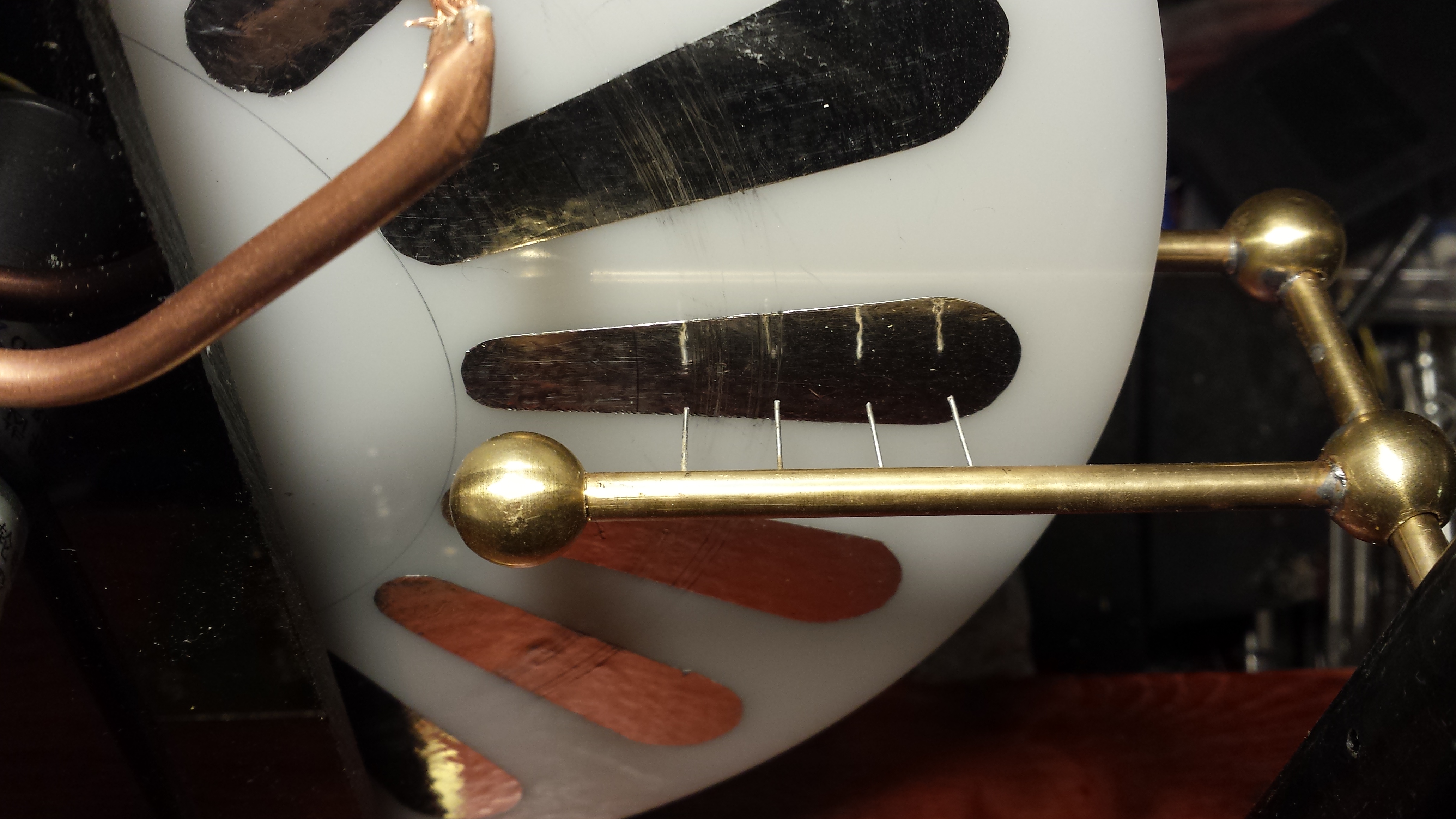 |
The collector wires were then cut to length when it was fitted to the machine. The inner charge collector was left tight, but un-soldered so it could be moved to set the gap to the disks. |
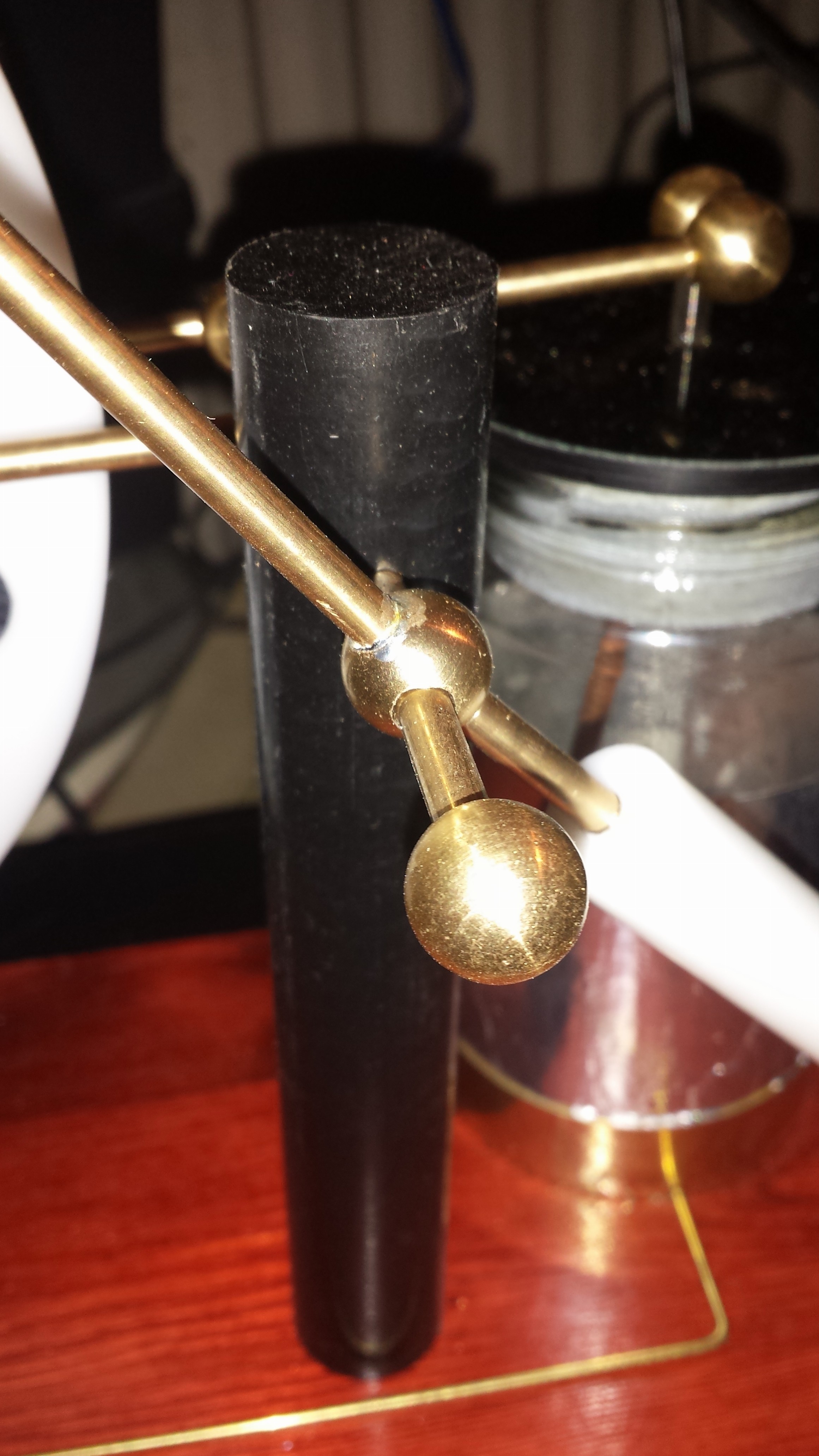 |
The charge collectors and terminals hare held up with a black piece of black nylon rod. The 5mm brass goes through this and is retained by a 3mm grub screw so the position of the charge collectors can be adjusted.
The two terminals are attached to brass rod terminated in a drilled through ball connecting it to the charge collectors. A short piece of nylon forms a handle and a short piece of threaded rod screws into a tapped hole . This allows the terminal to be adjusted and fixed in to position by turning the handles. |
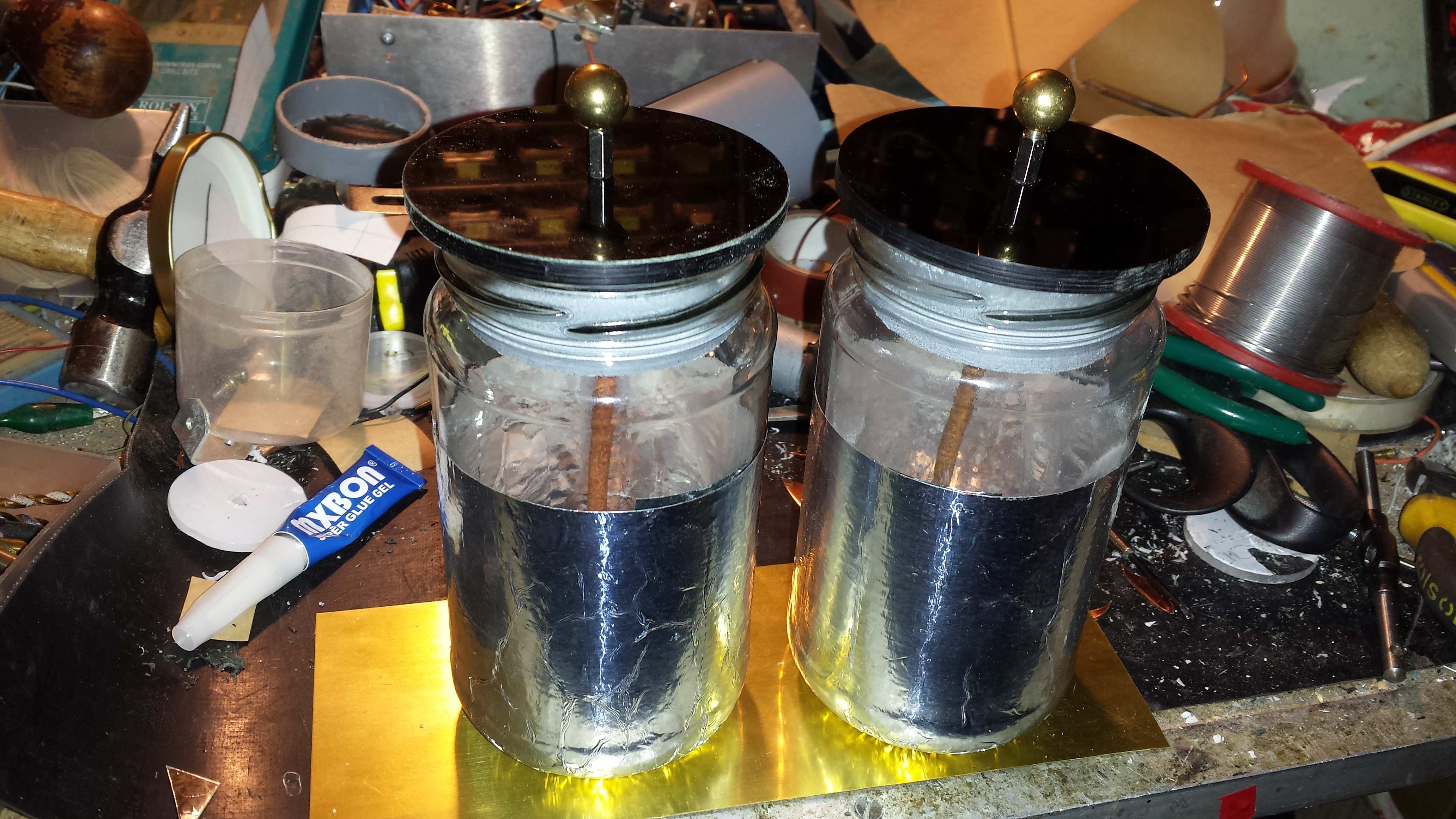 |
Two leyden jars details of their construction details at http://www.extremeelectronics.co.uk/hvexperiments/dry-leyden-jar/ |
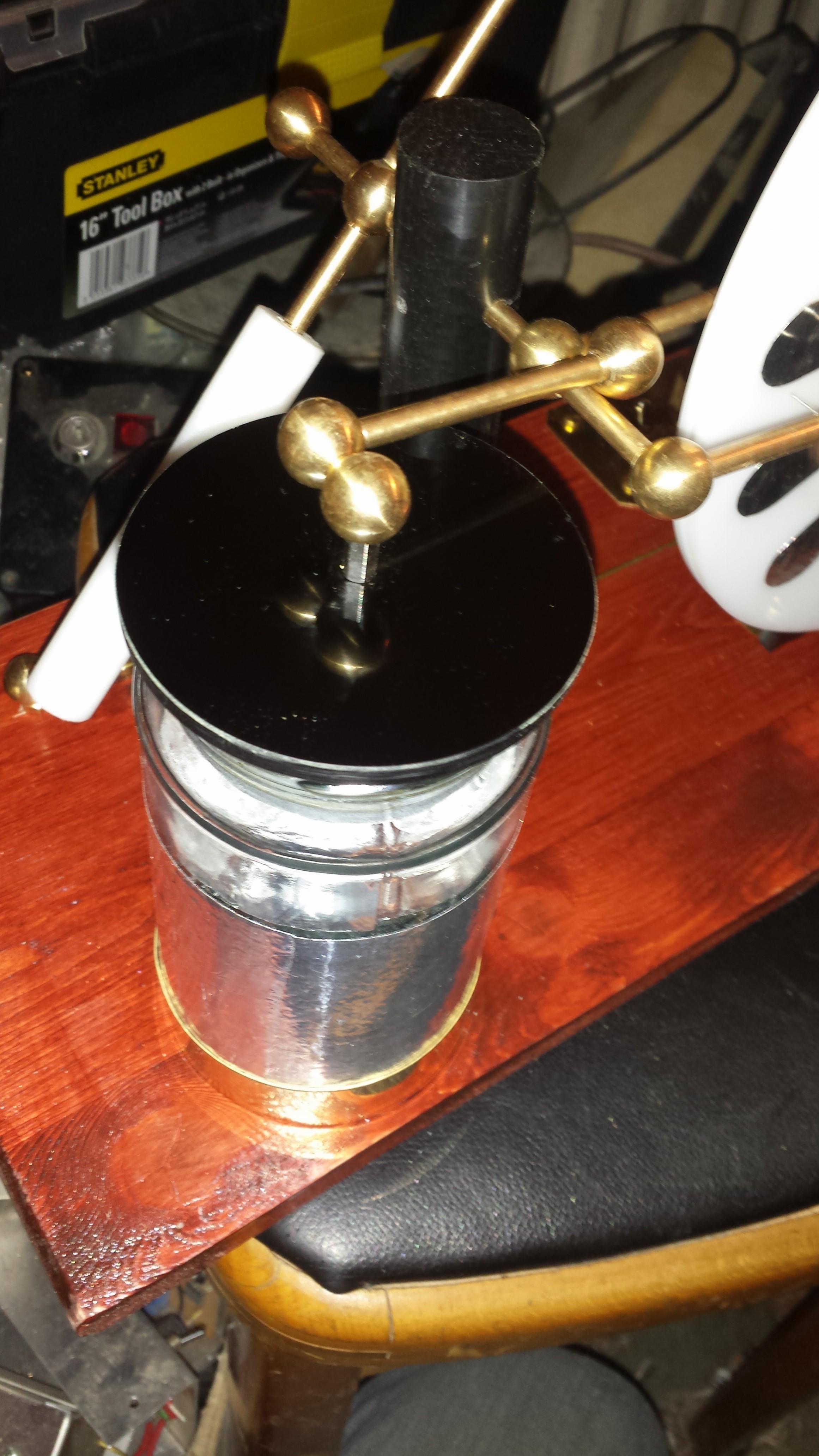 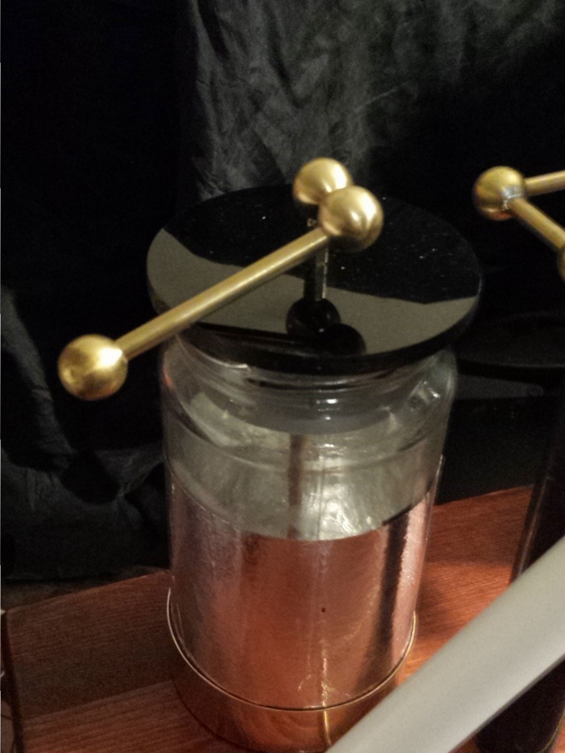 |
The leyden jars are “switched” by moving two hinged rods of brass. This allows the discharge to be continuous and low current or intermittent and high current. |
 |
Charge collectors disks and motors. The two leyden jars are joined by a 2mm brass earth wire that is also attached to an earthing post. |
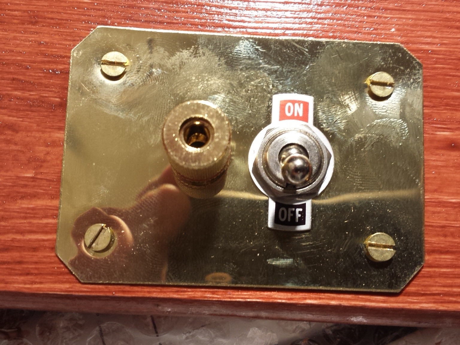 |
The control panel, with the earth post and on/off switch for the motors. |
 |
Underneath the base, motor wiring and batteries. The base is made from a 600mm pine shelf, that I stained to a dark mahogany |
  |
The base is raised up so that the batteries can fit underneath. A 10mm brake pipe connector is screwed into the base and a 10MM threaded ball added to each corner. this raises up the base by 20mm |
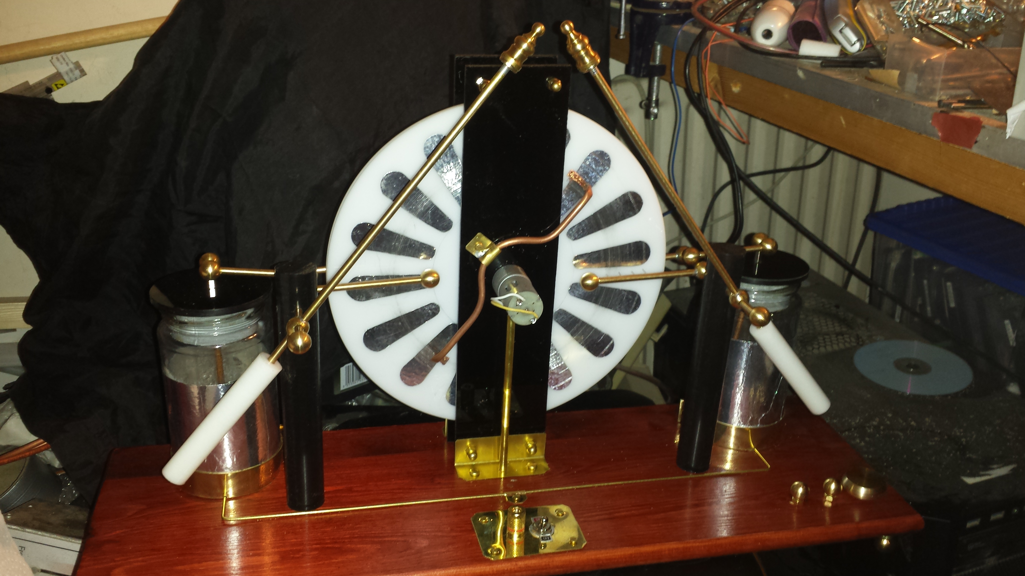 |
Front of the completed wimshurst machine |
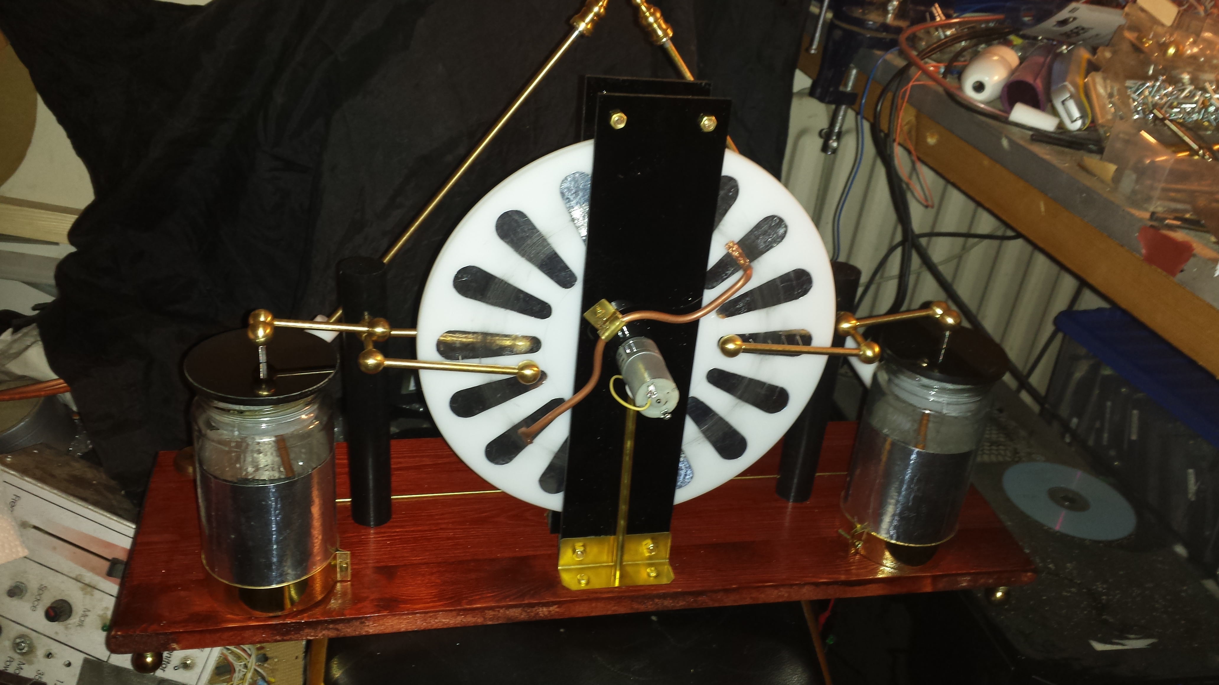 |
Rear of the completed wimshurst machine |
 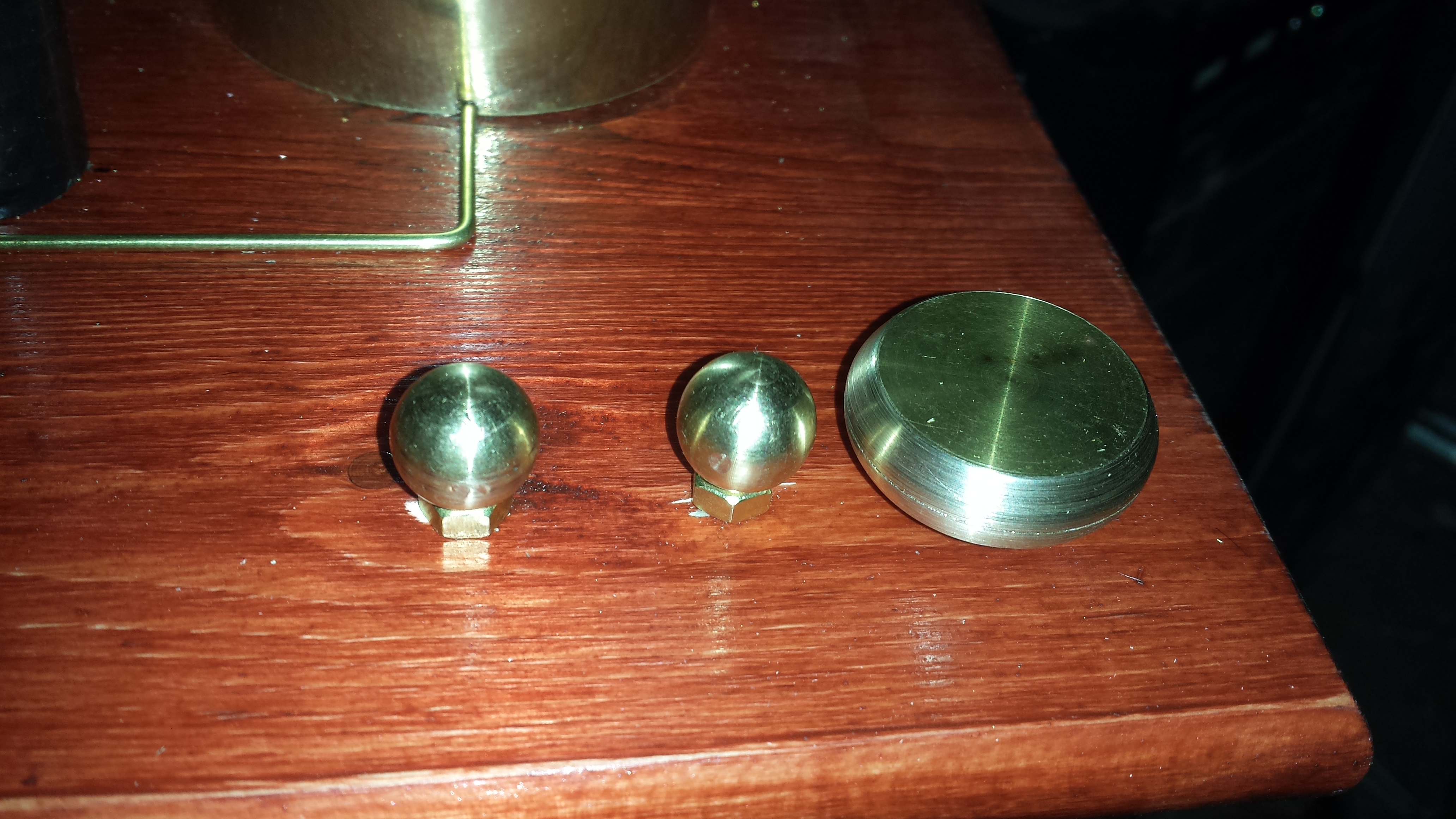 |
A selection of terminals can be exchanged by screwing them on to the terminal bars. There are 2 fancy finials, 2 14mm balls and a flat plate. The flat plate was made by soldering to 38mm brass plumbing blanking plates together and filing the edges in to a rounded shape. The terminals can be stored on a set of 5mm bolt ends attached to the base. |
|
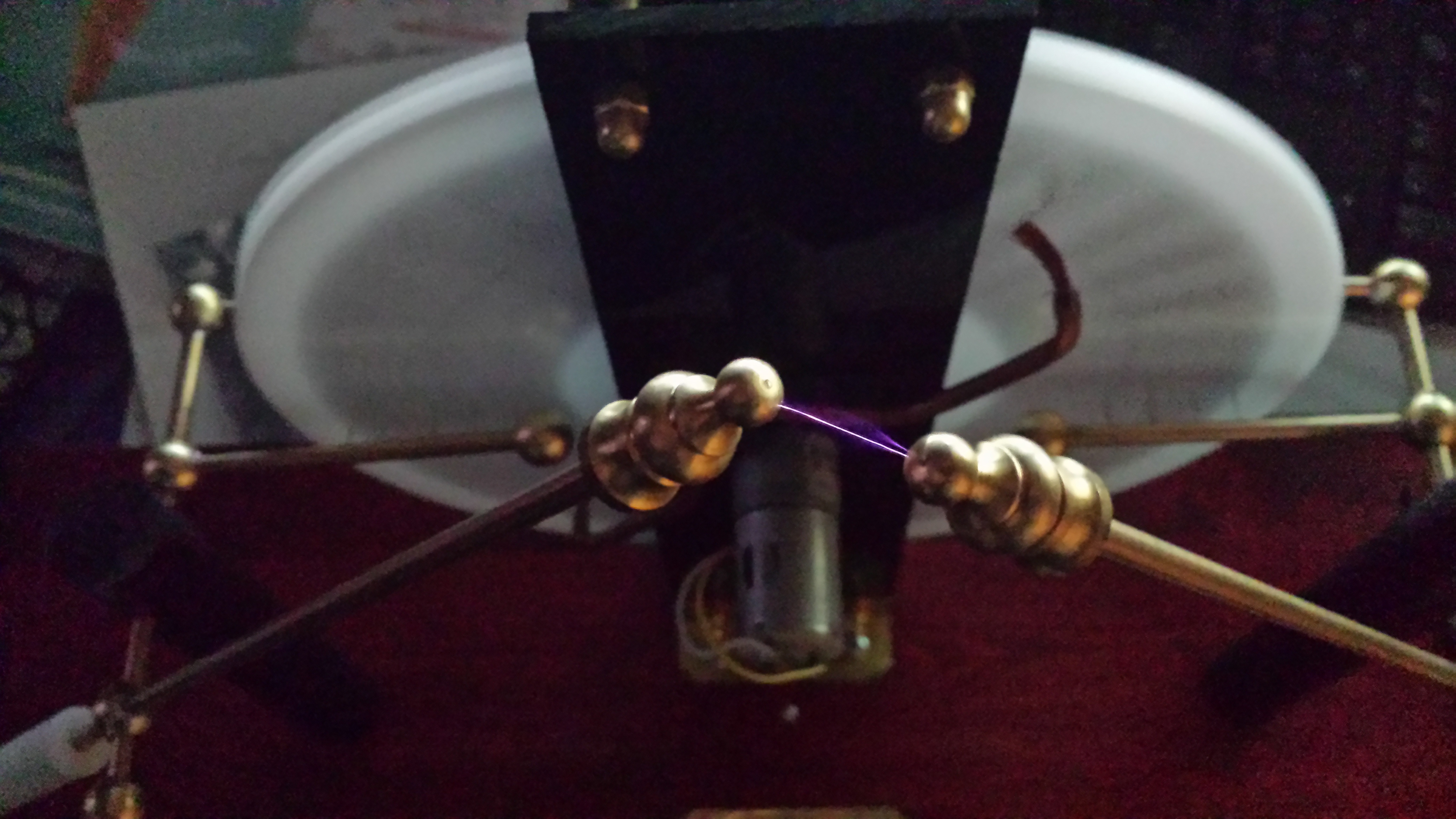
Sparks with the leyden jars disconnected. |
 |
The finished wimshurst machine running un-attended |
Wimshurst Spark Gallery