 |
Joan (of arc)
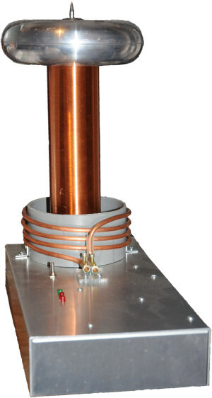
Joan is a portable DRSSTC similar to Sprite but with many improvements.
These include:-
Microprocessor controlled.
Full Bridge Driver
Primary Current feedback
Computer Control via RS232.
Primary: 4T 5mm copper pipe.
Secondary: 200mm tall, 1500T enameled
wire former 55mm diameter. wound
with 0.125mm Wire
Topload: 40mm x 400mm Toroid.
Joan runs from a pack of 10 NMH AA cells giving a 12VDC
supply. This is fed into a small inverter to give 350V DC bus voltage to the Bridge.
The Coil is controlled by a PIC 16F690 micro controller. This controls:-
Burst Length,
Burst Repetition rate,
Number of Bursts
This Controller also allows the Coil to be fully controllable via RS232 from a PC (see opto-isolator below).
The controller also has the ability to implement Over Current Detect (OCD) by using the micro's onboard comparator, but at the moment I am having severe noise issues, so this feature is disabled.
There are two push buttons for controlling the coil, one is a "mode" button and allows the selection of a set of preprogrammed burst lengths, burst rates and burst repetition lengths.
The operation of these buttons can be programmed and stored from the RS232 interface.
|
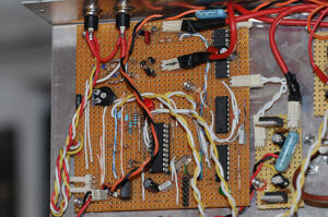 |
Microprocessor
The coil is controlled by a PIC 16F690
This allows the usual DRSSTC functions (including the interrupter) to be achieved in only 4 Chips.
The two chips in the top right hand corner were a pair of microchip drivers that would not supply enough current and are now replaced by a pair of IXYDD414 drivers on the small board bottom right.
The board takes its input from two push buttons for control and from a CT to give OCD.
The variable is to set the max OCD current level via the onboard comparator. At present this is disabled due to noise issues.
There is a 6 way header at the bottom of the board to allow for in circuit programming of the microprocessor.
The Main Circuit Diagram
|
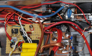 |
Inverter
12V is not enough for a decent spark !
So the 12v from the battery pack is inverted to 350VDC by a SG3525 PWM chip driving a pair of IRF460 MOSFETS in push pull.
The output from these goes to a single 25mm Toroidal ferrite.
This Ferrite ring has 3t-0-3t for the primaries and 125turns on a secondary. The output is then rectified and stored in a 400uF capacitor under the bridge. The whole inverter runs at 50Khz and is voltage controlled to save battery life. When the capacitor is charging the inverter provides around 80-90W of power.
Inverter Circuit Diag.
|
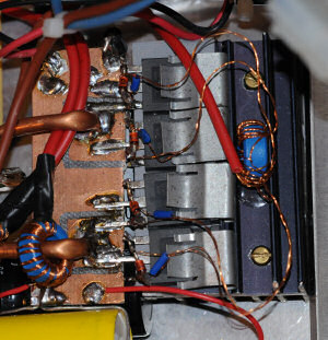 |
Bridge and GDT
The bridge is made up of 4 x STGW30NC120HD 1200V 30A (135A pulsed) IGBT's. I am of course pushing these up to 200A with very short burst lengths.
You can also see on of the pair of CT's to the left, One gives a phase signal to the driver and the other one is for over current detect.
The main reservoir capacitor is under the bridge and is bypassed with a 0.1uF @1Kv.
The drive is via a gate drive transformer which has one 12T primary and four 18T secondary's this ensures that I get a solid +/-15v gate drive which is clamped by 15V zenners on each IGBT gate.
|
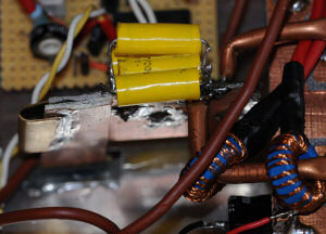 |
Primary Cap, Ct's and Feed
The Primary is fed via a 0.4uF capacitor made from an assortment of smaller caps, this allow me to tune the coil by adding or removing capacitance.
The feed to the primary is via a set of double sided PCB "feeders" which reduces the out of circuit impedance.
A close up of the primary feed can be seen here
|
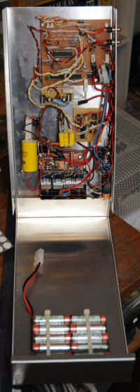 |
Complete Unit Inside
This is how the whole lot fits together. into a single case 300mm long, 200mm wide and 55mm deep.
There is now the addition of a charging socket on one side so I can charge the coil without taking the batteries out.
|
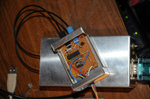 |
Opto-isolator Tesla Coil end
This box is powered from Joan itself and is a plug in extra.
It allows a degree of isolation (200mm worth) from the tesla coil itself so I can safely attach a laptop to program or control Joan
On the Transmit side there is a single transistor that takes the PIC's output and drives a high speed transmitter LED.
The receive side takes the signal from the opto-diode and amplifies it with a single HEF4049. This is then fed directly into the PIC micro controller.
|
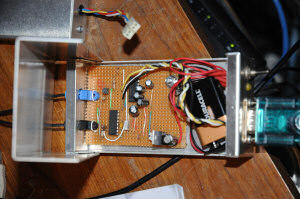 |
Opto-isolator PC end
This is the PC-Side of the opto-isolator. As the (cheap) RS232-USB dongle I use only supplies 5V, I need to have a small battery to give the current for the transmit LED. this is achieved with a single transistor.
On the receive side, to ensure the isolator is compatible with "real" RS232 the signal from the opto-diode goes via a HEF4049 amplifier and a MAX232 chip to give +/-12V to the PC.
Both units together will give a throughput of 19.2Kbd.
|
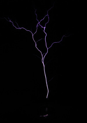 |
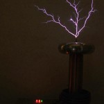
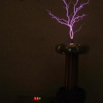
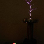
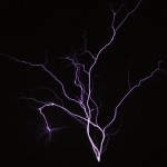
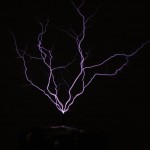
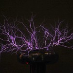
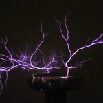
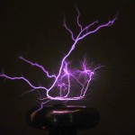
Sparks
Joan will produce 12"+ arcs to air using a high repetition rate (1Khz) over 10 bursts. Unfortunately at this rate the capacitor needs to be re-charged completely which can take 2-3 seconds.
Using variations of different burst lengths, repetition rates and number of repetitions smaller discharges can be maintained with faster recharge rates.
|
File:http://www.extremeelectronics.co.uk/old/coils/joan/joan.php
Joan Sparks
Tesla Coils and High Voltage