
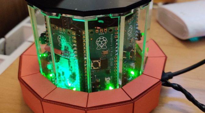
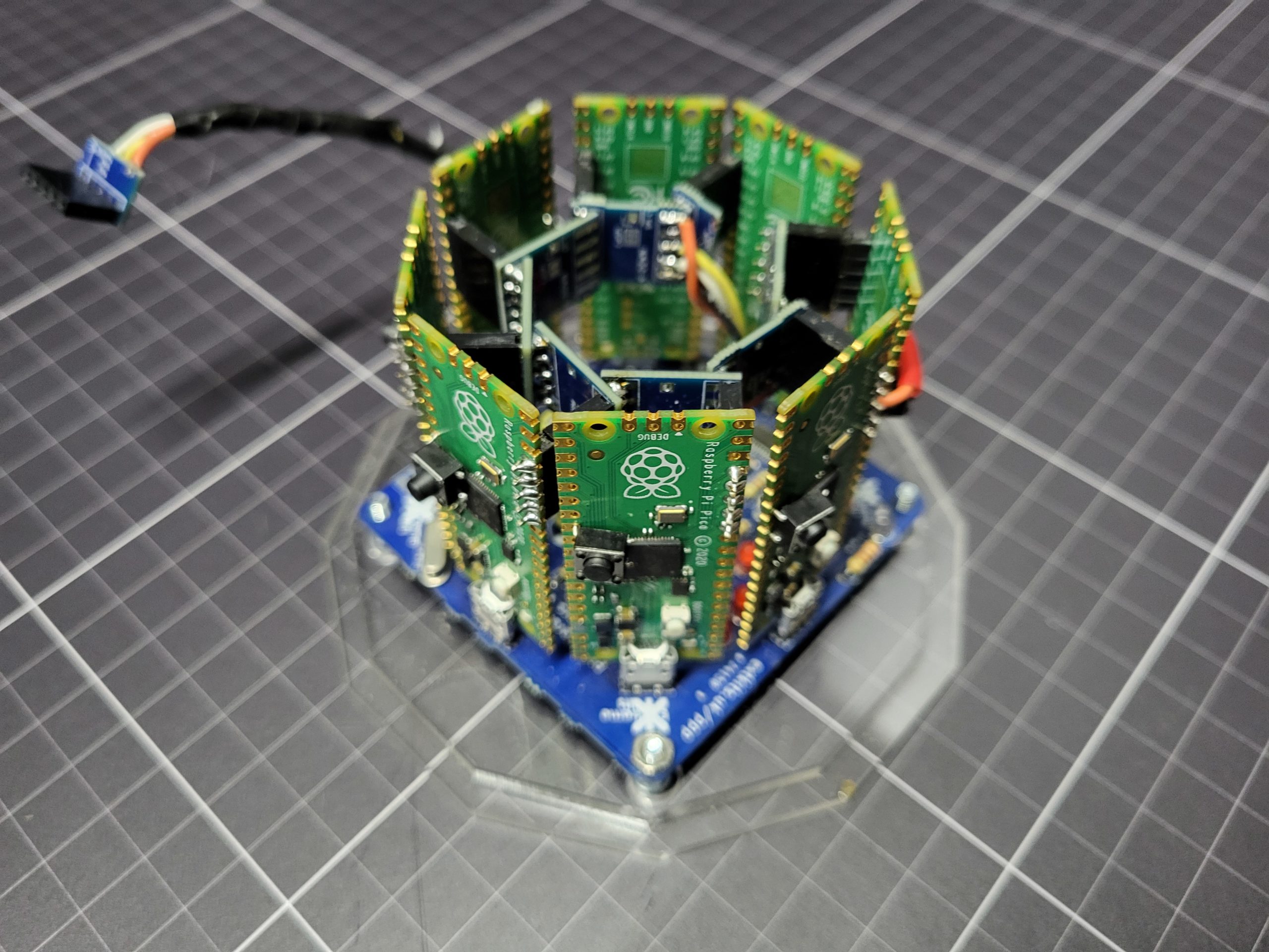
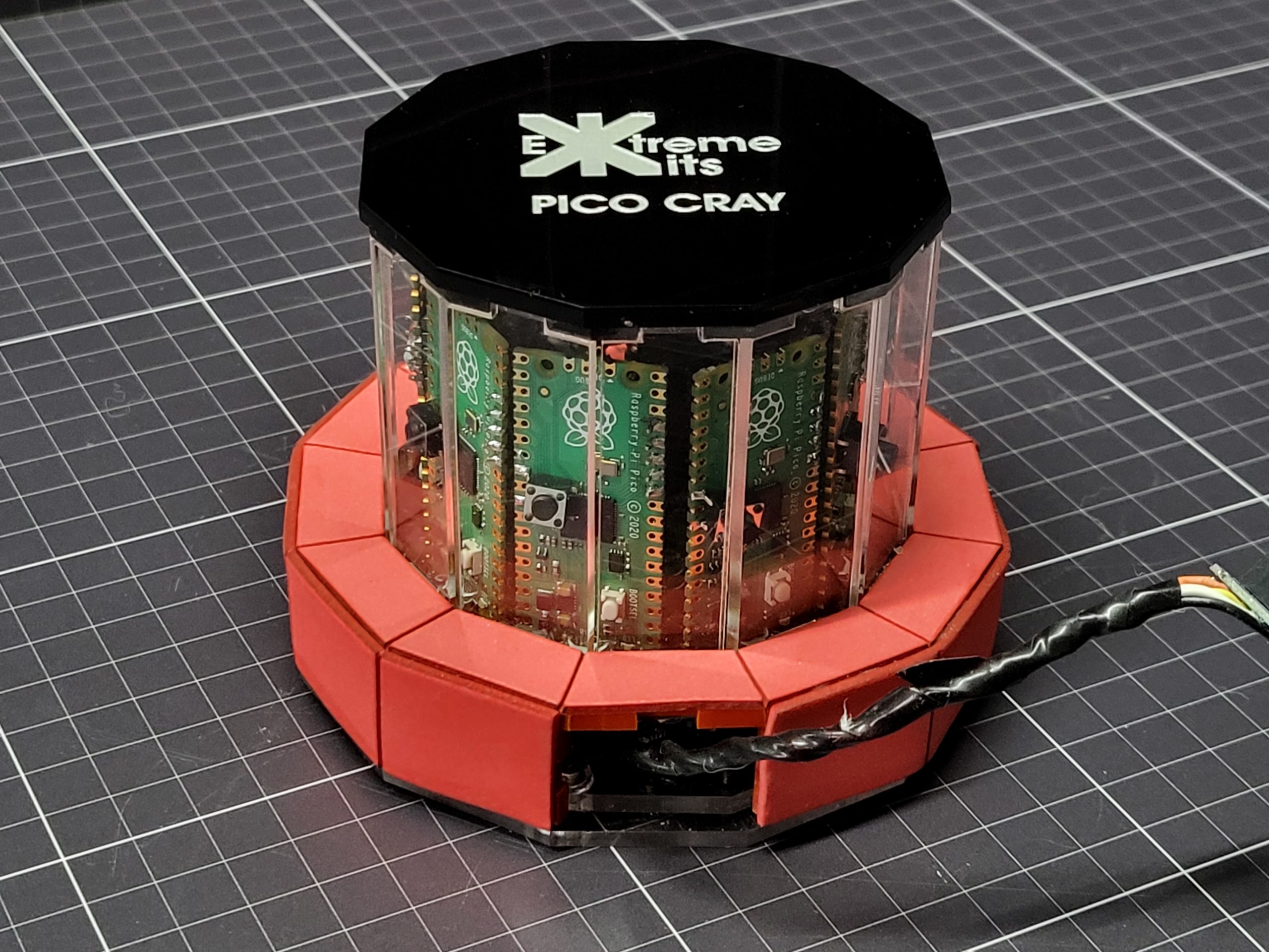
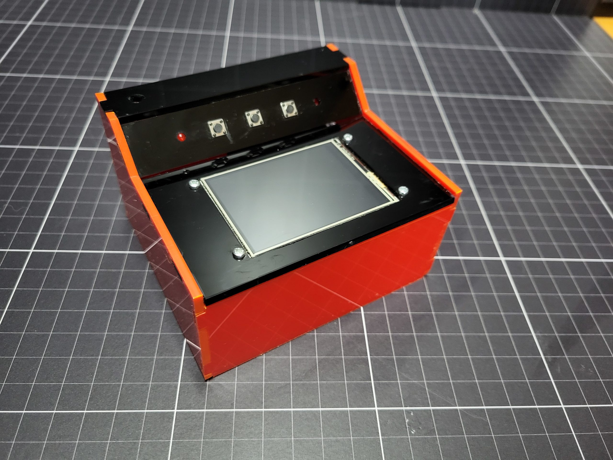
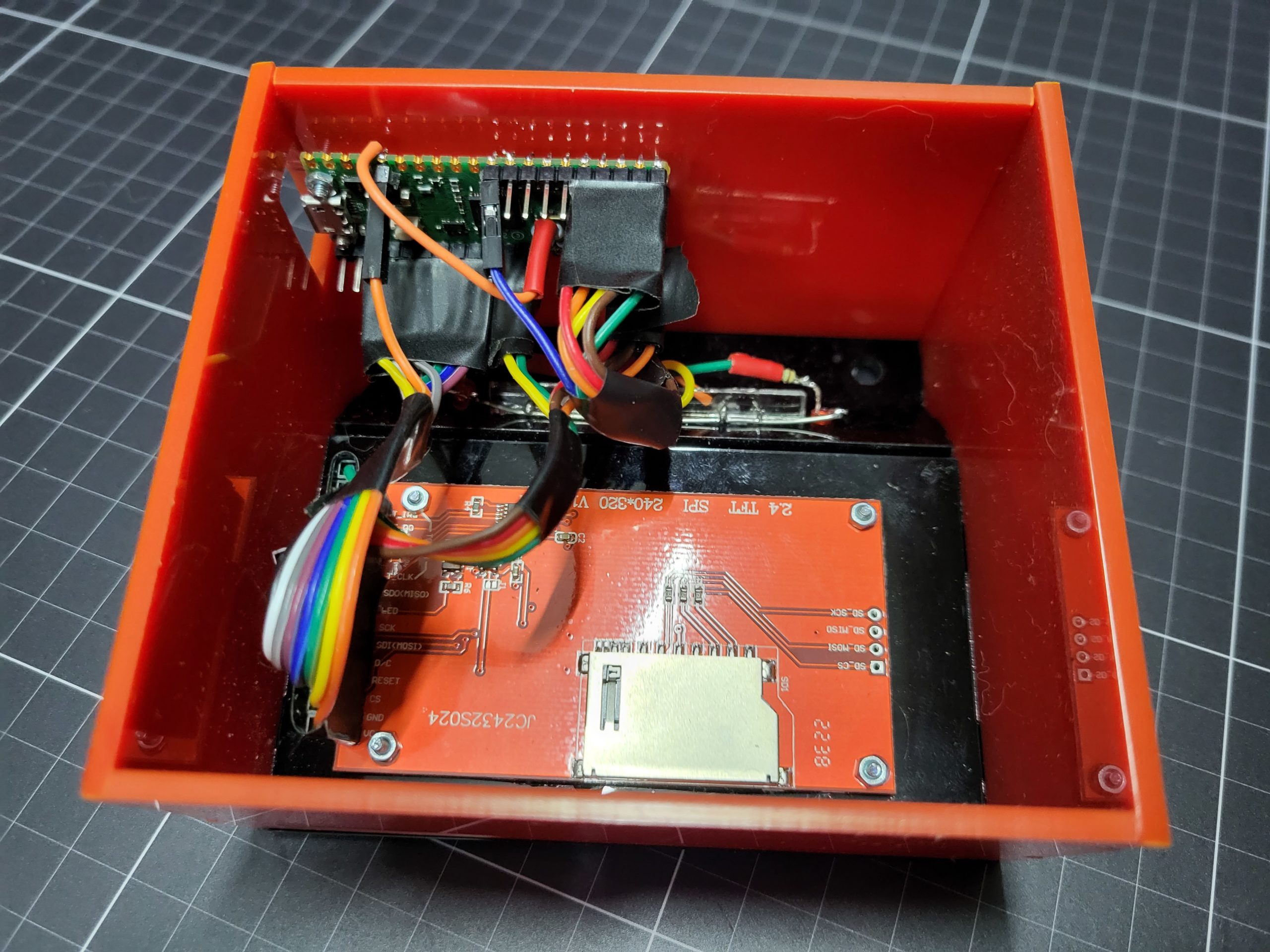
The Pico Cray is a cluster of 8 Picos and a controller Pico. All Picos are connected in parallel by an I2C bus. The controller is designated by one GPIO being held low, the processor Pico’s addresses are allocated automatically. The Controller Pico has a 320x240px display connected by SPI and a couple of buttons. As all of the Picos run the same software updating the cluster is easy.
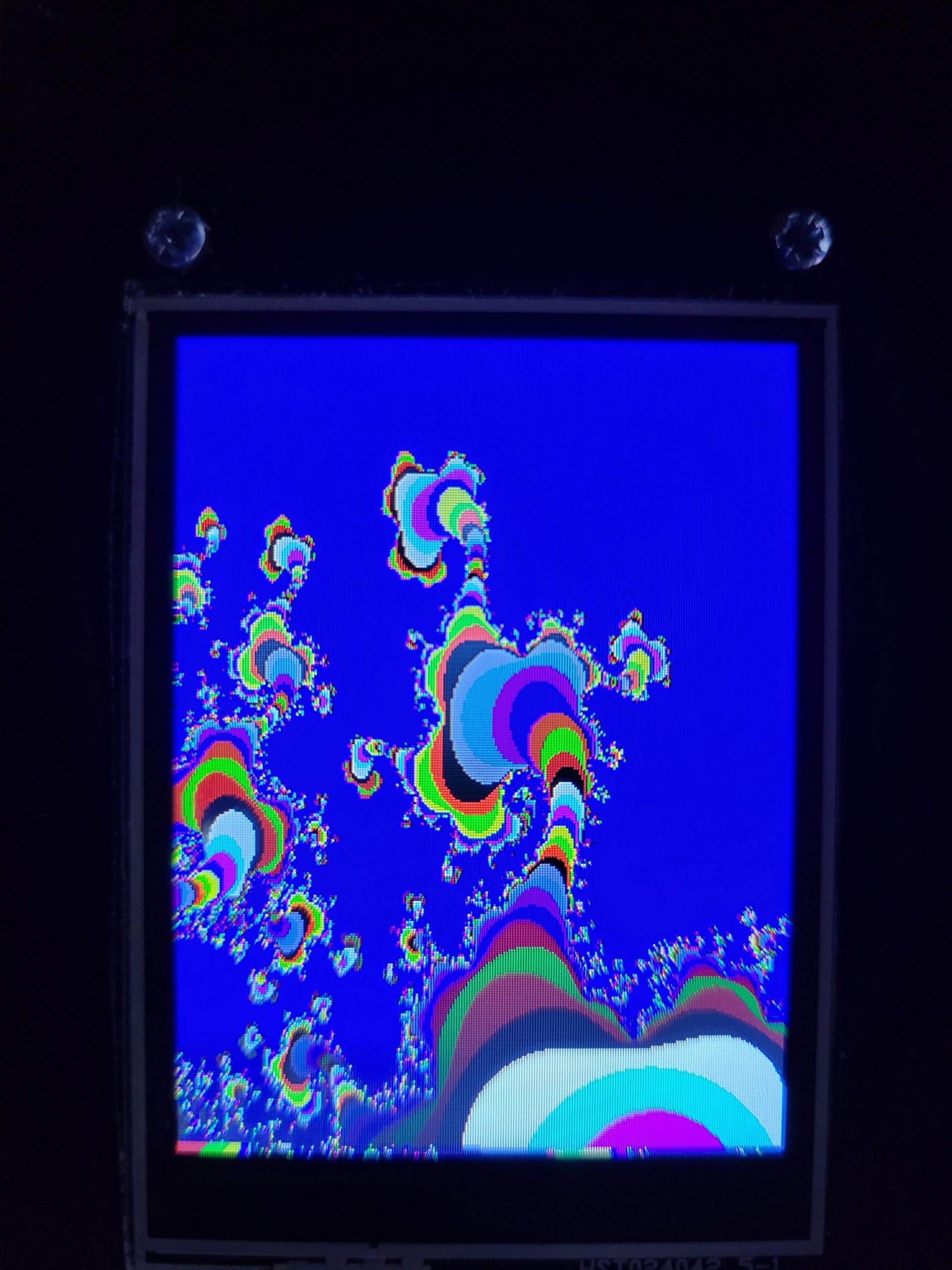
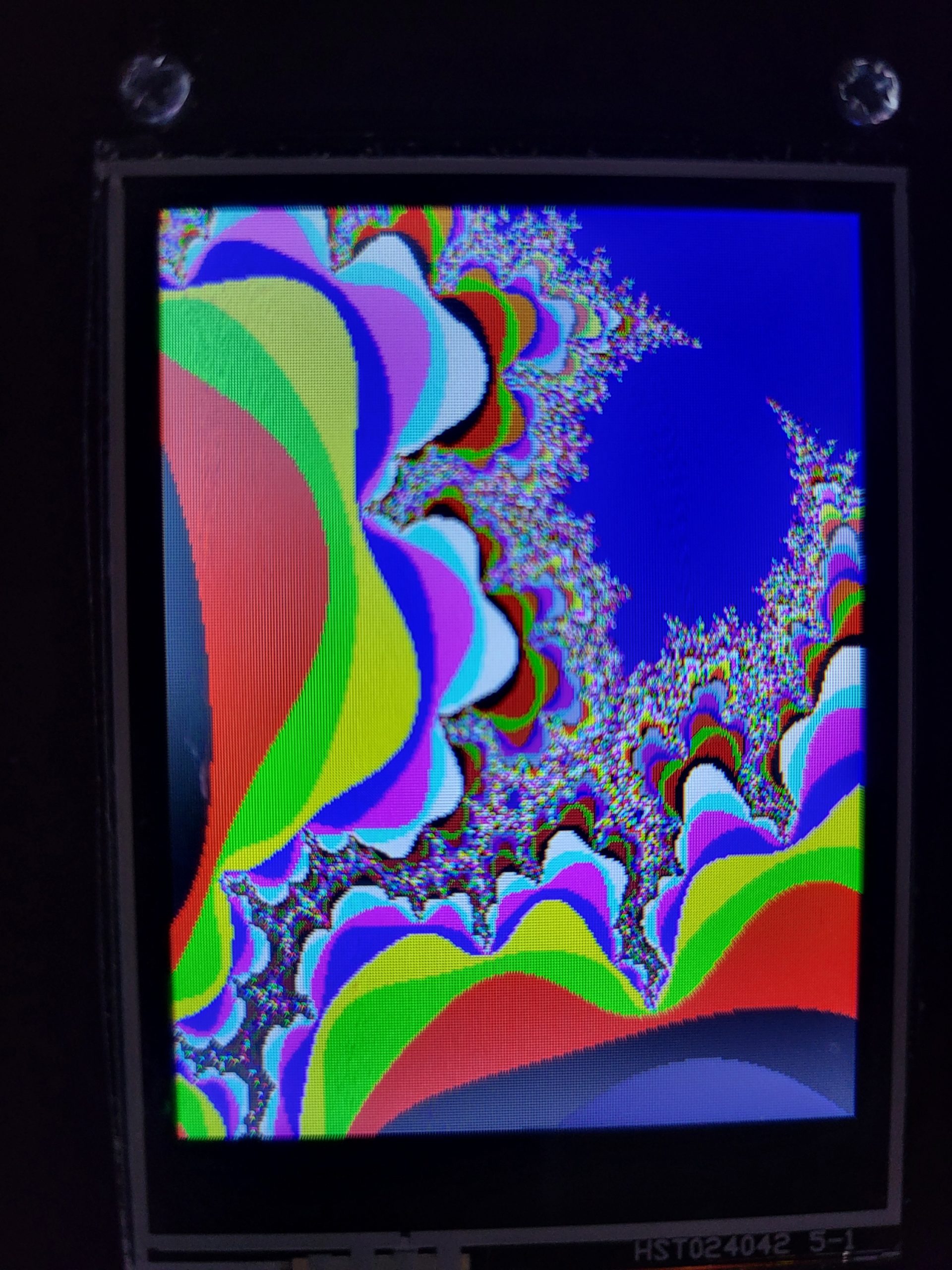
Currently the cluster is programmed to run a Mandelbrot program. With each processor Pico calculating 120 points before returning them to the Controller.

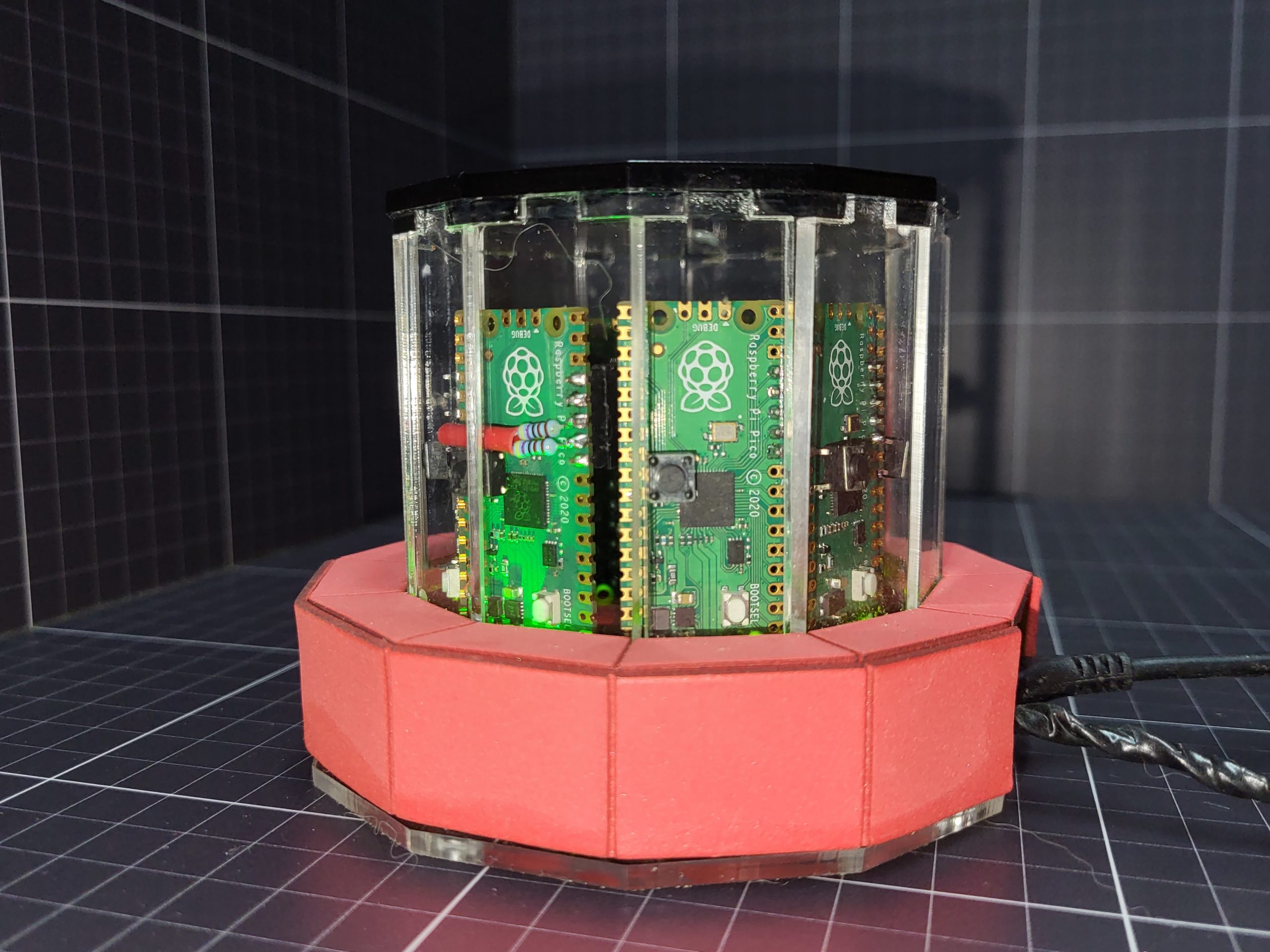
The case of the cluster is built to mimic a classic Cray1 Supercomputer. Including a padded seating area and the controller housed in a console desk (although not to scale with the cluster)

Building the case.
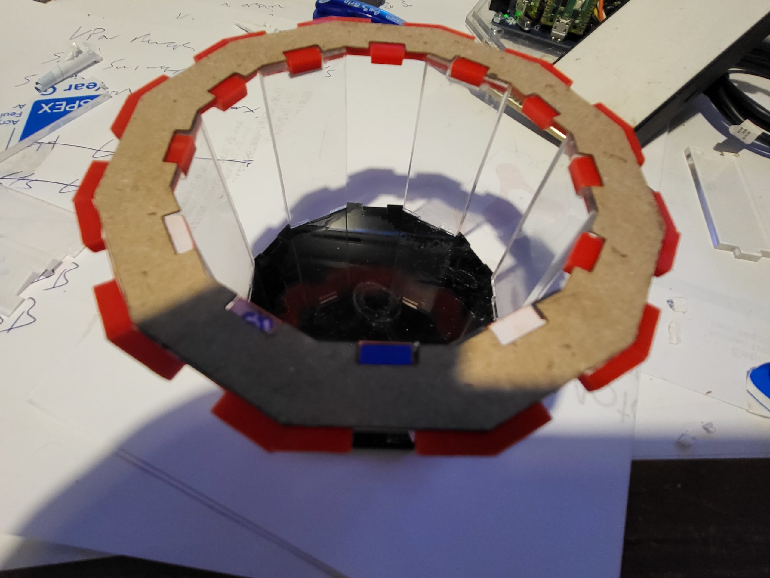
The case was made form a combination of transparent and red/black acrylic to mimic the original Cray1 design. To follow with this style the seating around the central column was padded with foam.

To keep everything together, each acrylic piece was tabbed, and the bottom ring was also held together by being glued to a cardboard ring, this meant that I only needed 3 hands, out of the available 2, to try to get it all to join whilst the glue dried.
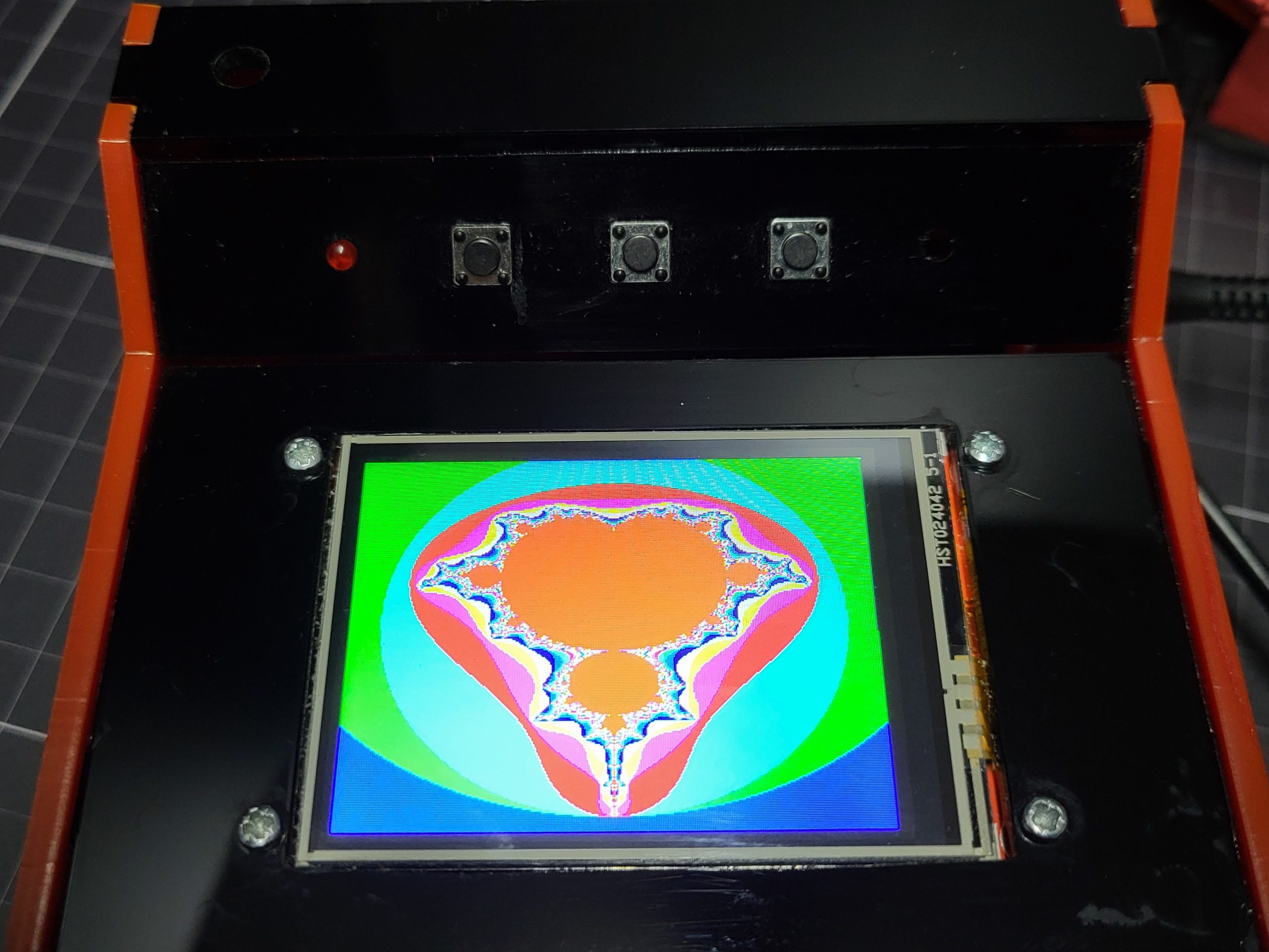
The console was manufactured in the same way, pieces of black and red acrylic with tabbed were glues together to hold the display, a row of buttons and the controller Pico.

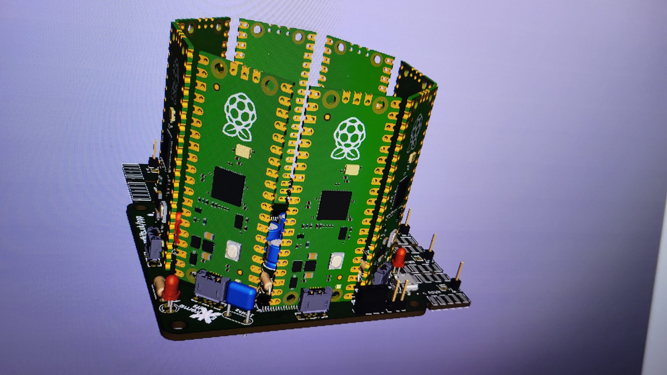
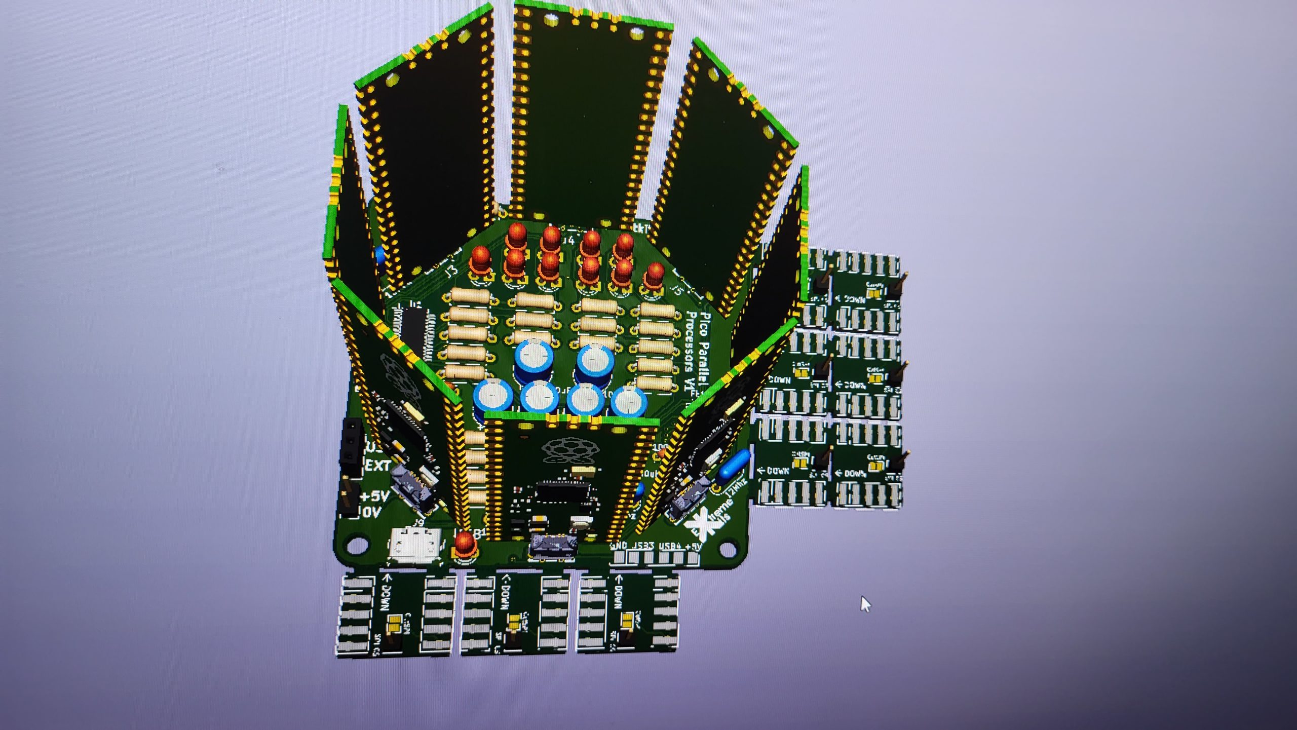
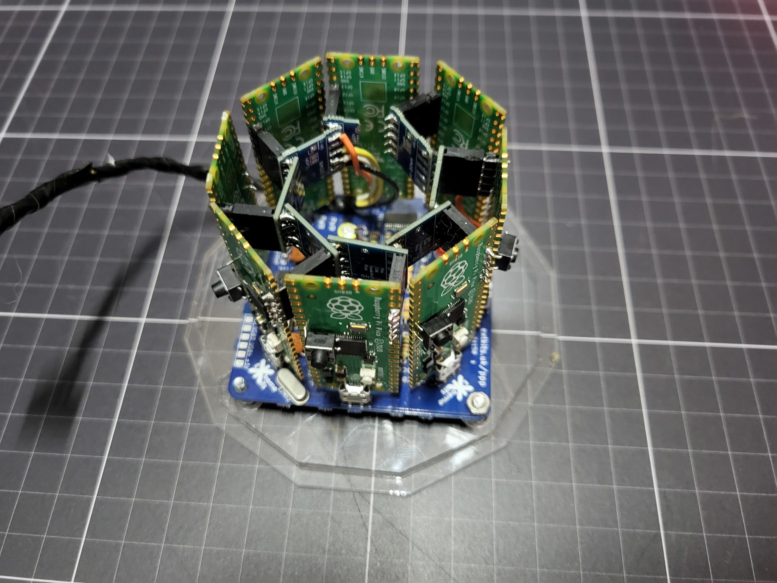
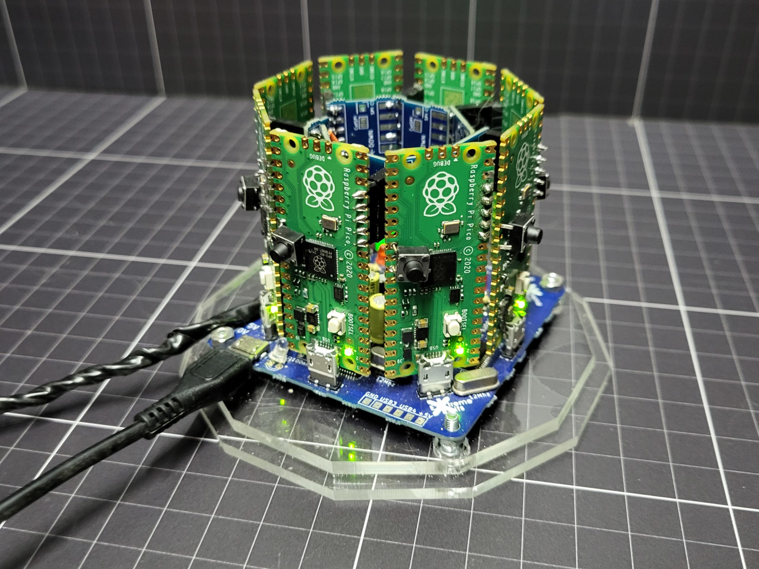
PCB
The PCB for the Processors is constructed to hold the 8 Pico PCB’s in an octagon, In such a way that all of the Pico’s can be powered by the USB connector. The I2C bus and the “assert” line is extended around the Pico’s with a number of daughter PCB’s soldered together at a jaunty angle.

The Base PCB is actually an 8 port hub, but due to issues with Linus/Windows and the Pico’s USB connection, it was found unworkable to use the hub for programming.
Mandelbrot
The test program for the distributed computer uses the Mandelbrot fractal for its test. This was chosen as its well known, easy to implement and gives a recognisable output. Also by its cartesian coordinate structure and as each point is stateless, very easy to split into a number of discrete calculations. Currently 120 points are calculated by each processor at a time in what Ive called “A Lump”]


Software
Testing the software was done with a strip of vero standing in for the PCB, this enabled rapid reprogramming and the ability to see the USB serial on three processors and the controller all at once.

You can also see the termination resistors on one Pico, these were later changed to 2x 4K at each end of the I2C bus.
The Picos in the cluster are called Processors and Controller. The Controller is designated by GPIO22 being pulled low.
On turning on a Processor, it will wait a random amount of time, and if the assert line is not already high, it will set assert high, and listen on 0x17 on the I2C bus. If the assert line is already high, the processor will wait a random amount of time
The Controller will see the assert bus high and know that a processor is waiting to be added, It will send a free I2C address to that processor. (none of the others are listening)
On Receiving the I2C address the Processor will change its I2C address to the one given, set its state to READY and relinquish the Assert line.
Once there is at least one Processor in the READY the controller will send a task, currently this is an XY coordinate and a step value ( 3 doubles) for the Mandelbrot calculation. The Lump size is currently compiled in as 120 calculations. A note of which processor and which X & Y coordinate it was sent is also saved. The Controller finishes by setting the processors BUSY flag.
The Processor will continue allocating tasks until there are no free Processors.
When the Processor has completed its task, it sets its DONE flag.
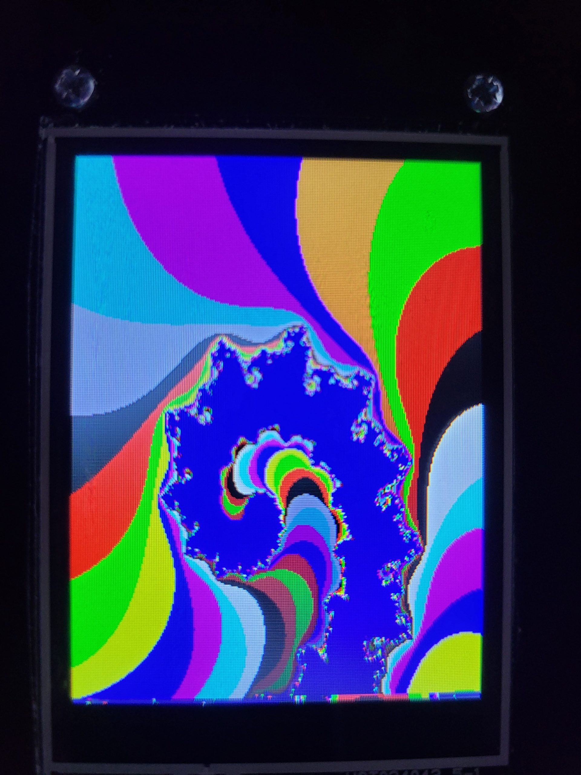
The Controller continues to scan each processor for its status, If it sees a DONE flag it will download the results, currently 120 unsigned chars representing the iterations of the Mandelbrot calculation.
A palette is applied to these values with a look up table to give a full 16 bits of colour that is then sent to the display as half a line (a full line is 240 pixels)
Detailed Software information can be found at
https://github.com/ExtremeElectronics/PicoCray
Want this as a kit??? Well ask at Extreme Kits and I may be persuaded 🙂