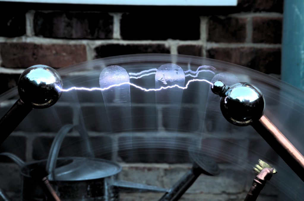
A project to make a Large Wimshurst electrostatic generator machine with 950mm diameter disks, eventually to break 1MV with 320mm sparks. (or better)
It all started with some discarded Covid screens, 1M square and 5mm thick.
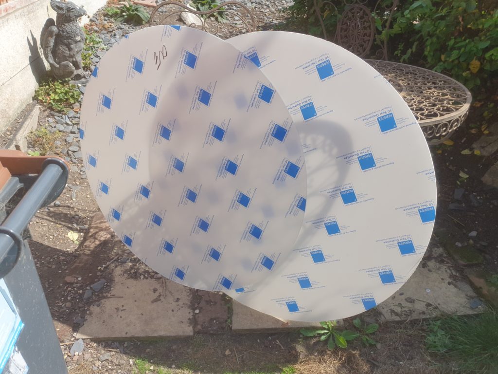
Annoyingly, they got repurposed before I got my hands on them, but the idea was set, build a HUGE Wimshurst machine. So I ordered a couple of disks, as big as I could out of a single acrylic sheet. This worked out at 950mm diameter
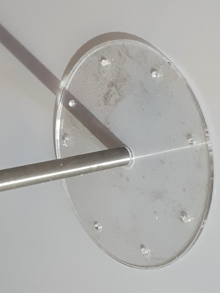
I’d planned for the disks to be cut with a 10mm centre hole, but of course I needed a better attachment to hold the not inconsiderable weight of the disks. I laser cut an acrylic template and drilled 8 guide holes.
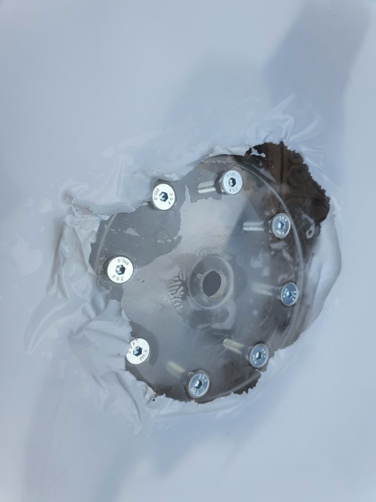
These were drilled out to 6mm and countersunk to allow hex head counter sunk bolts flush to the surface of the disks.
Unfortunately this left very little acrylic between the bolt head and the outer disk, so on the outside of the disk I glued a 3mm acrylic plate to strengthen the mounting.
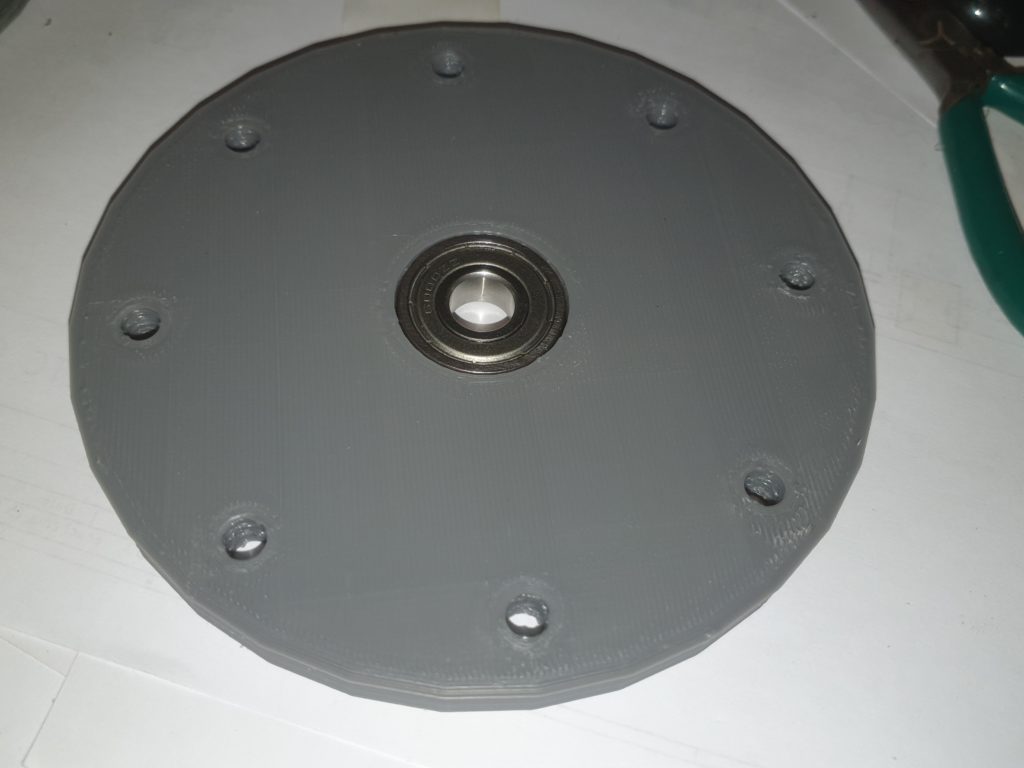
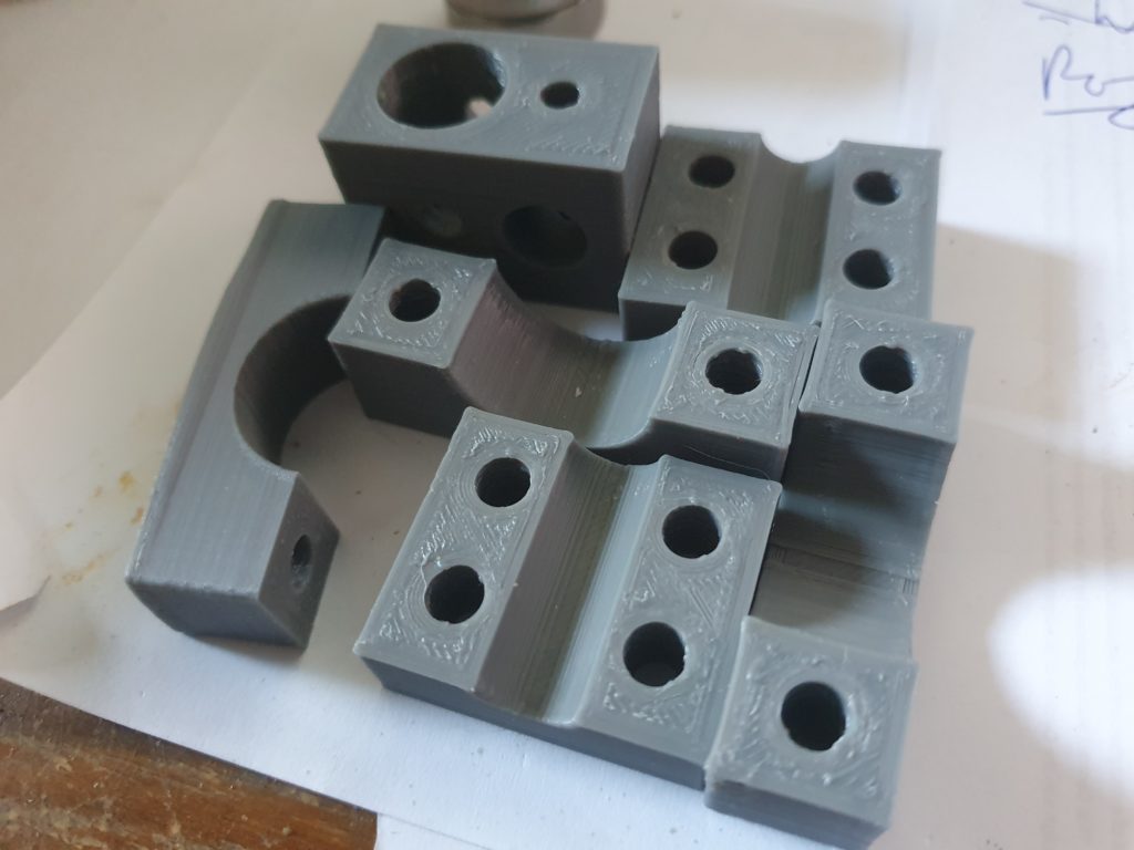
The bolts first go though a 3d Printed 8mm plate that holds a 28mmx10mmx8mm ball bearing.
There are a number of plates that are held together with the 8 m6 bolts. some laser cut and some 3d printed. Together they allow the two bearings to be 50mm apart to hold the disks perpendicular to the 10mm shaft.
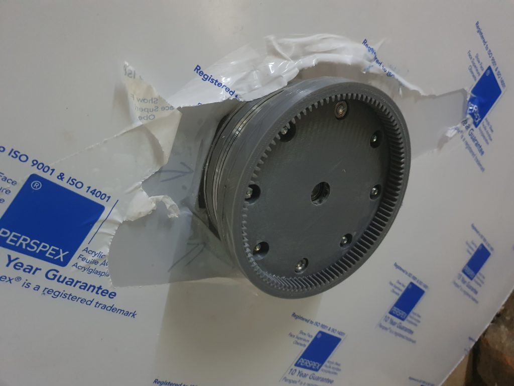
The last 3d printed plate adds an internal gear to the boss for the motor drive on each disk
The bolts are attached with nuts in sunken holes on the last 3d printed plate.
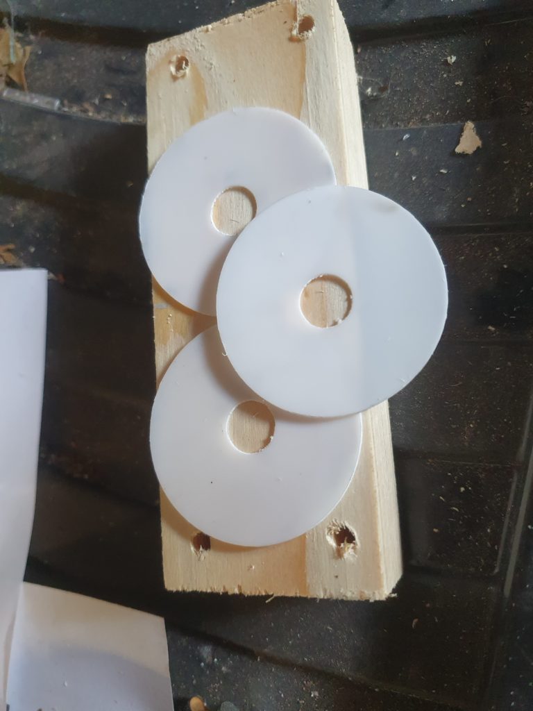
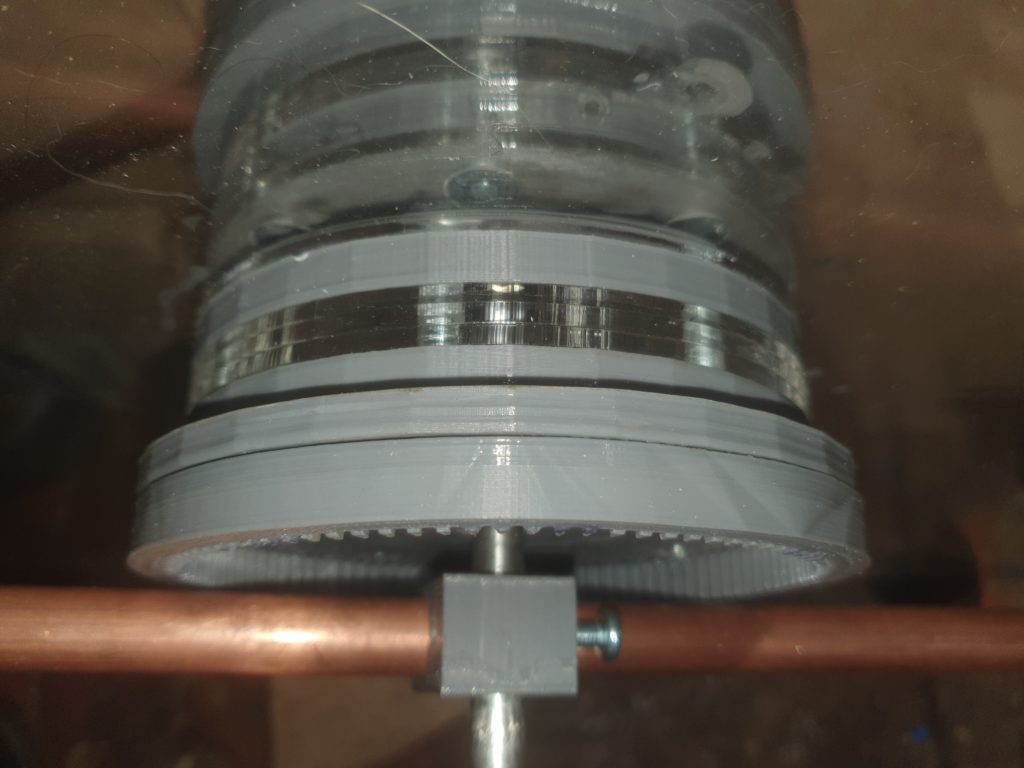
A series of spacers allow the disks to be accurately spaced away from each other. The two outer washers are PTFE to reduce friction as the disks will be spinning in opposite directions.
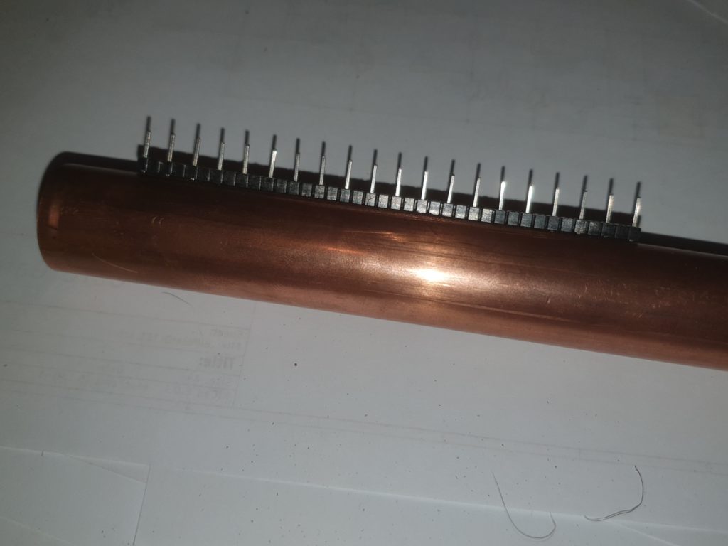
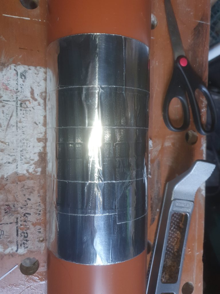
At each side of the disk are the charge collectors. These are used to collect the high voltages on a series of pins. Im using 2.54mm connectors with every alternate pin removed. These are glued into holes in a 22mm copper pipe
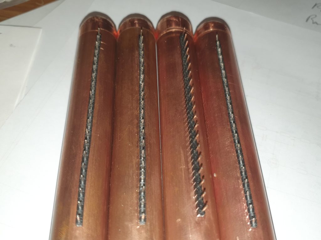
There are four of these in total (2 each side)
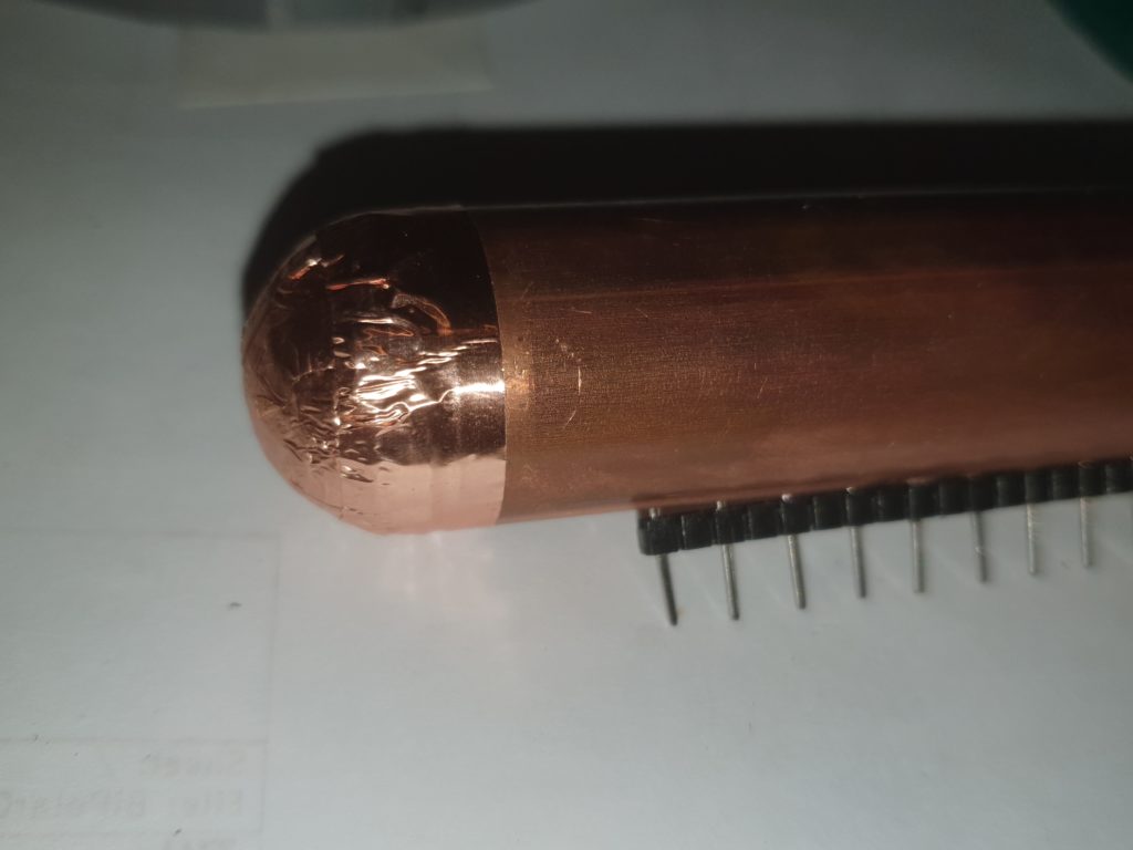
Then ends are finished off with copper tape covered 3d printed domes to reduce leakage of the high voltages.
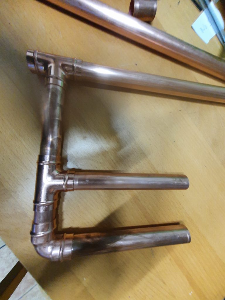
The charge connectors are attached to the discharge wands with more 22mm copper pipe
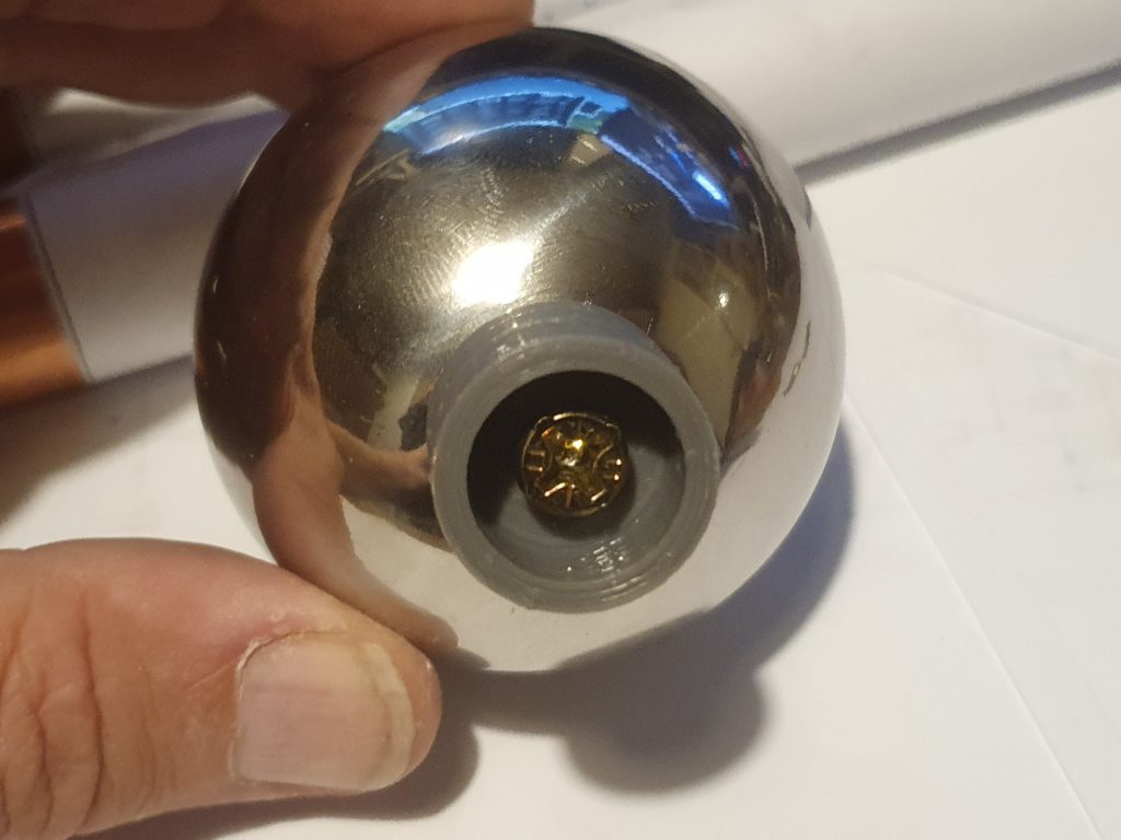
The discharge wands consist of a 600mm piece of pipe with a discharge ball at the end. These balls are 70mm Gazing balls (used in gardening) a
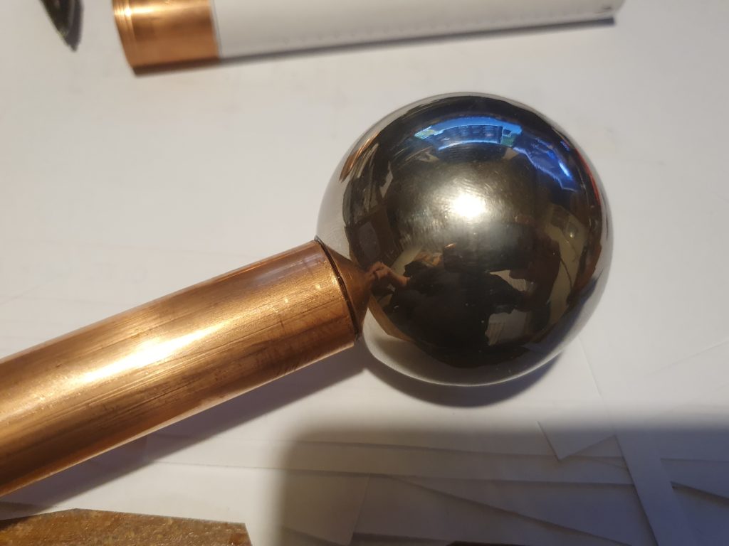
3d printed bung allows a single self tapping screw to attach the balls and are glued in to the end of the pipe.
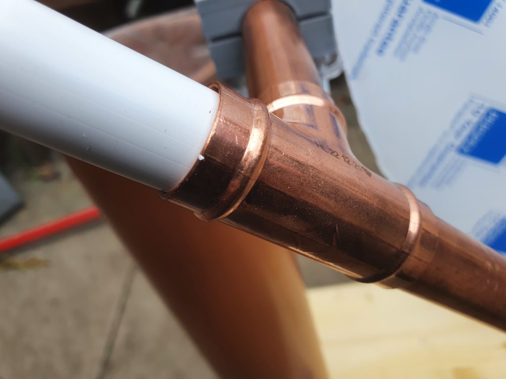
The other end of the discharge want needs to be insulated from the high voltage so I used a 22mm PVC pipe.
Unfortunately 600mm of copper and ball on the end weigh much more than a piece of PVC, so to balance them out and so they are easily adjusted.
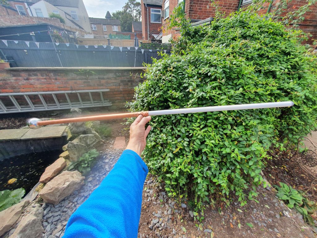
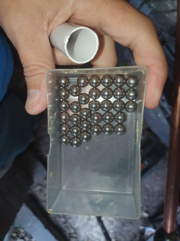
I weigh the end of the pipe with 8mm steel shot which balances out at the T-piece in the middle. These are retained with a bung
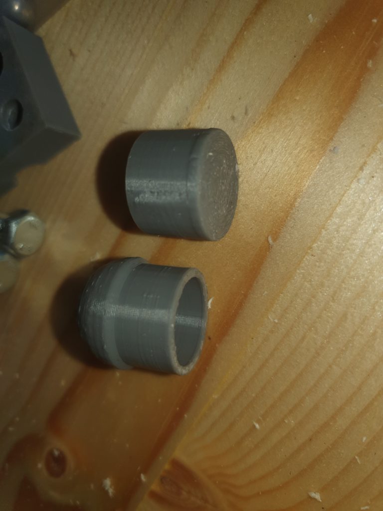
A 3d printed bung and a pipe dome finishes off the PVC pipe.
To make a Wimshurst you need sectors on the disk, The ideal number size and spacing is difficult to ascertain. More sectors give more current, but bigger gaps between sectors give higher voltage.
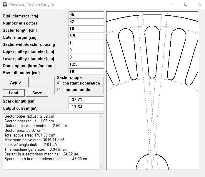
To help with this I use a program called WMD by , Antonio Carlos de Queiroz who sadly died recently. There was a huge amount of information at https://www.coe.ufrj.br/~acmq/wimshurst.html currently this link isn’t working and I hope some where there is a copy of his works on electrostatic machines.
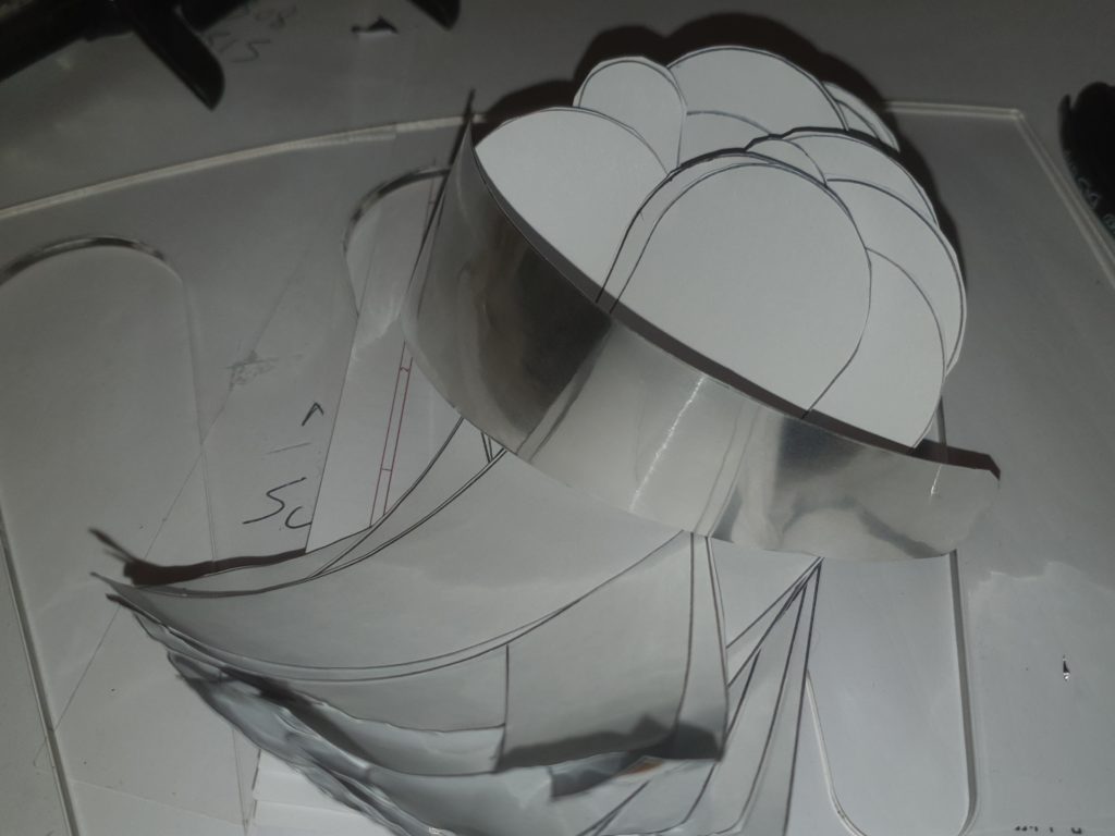
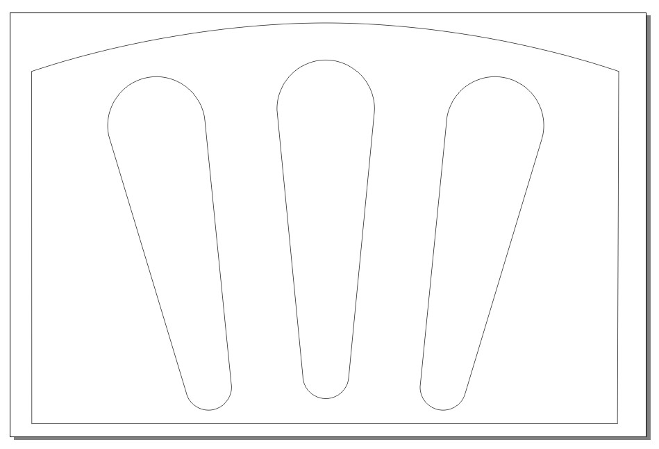
I oped for 32 sectors per disk with 20mm spacing. The Sectors were cut from aluminium fire protection foil tape. There are 64 (two disks of 32 ) in total. I laser cut a template, drew around it with a pen on to the backing of the tape, and cut them out by hand.
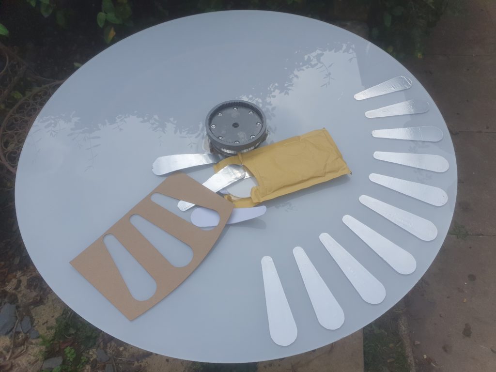
I laser cut a template to assist with placement and carefully stuck the sectors onto the disk.
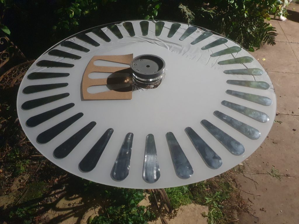
Yey, one disk done, one to go…
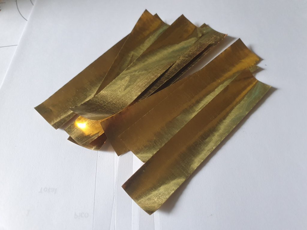
The neutralising bars need brushes to lightly touch and discharge the sectors as the disks rotate. I made these from 4 pieces of 20mm wide brass foil 0.05mm thick
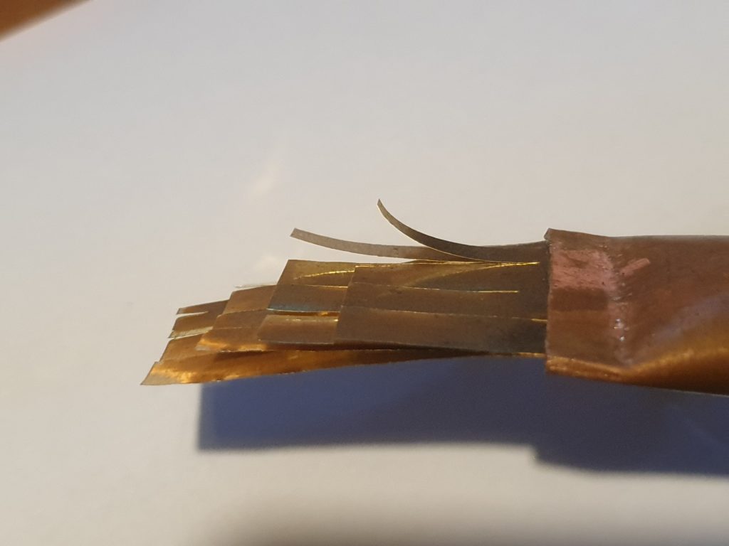
These were crimped into a short piece of 12mm copper pipe and the ends cut into 5mm strips
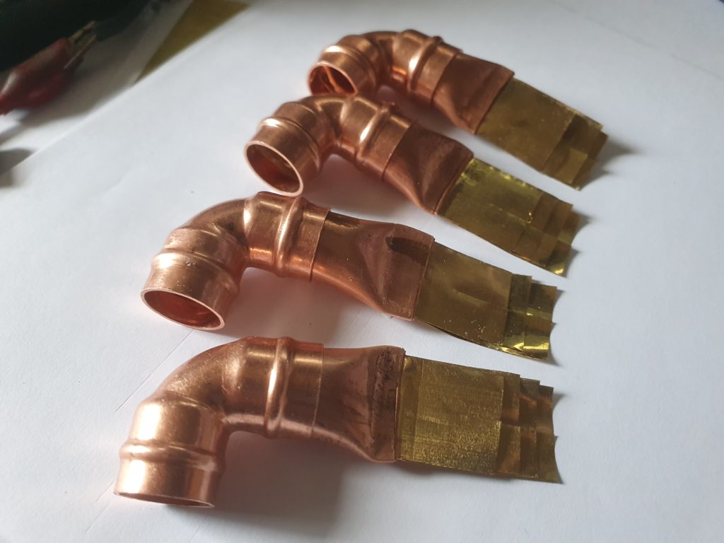
These were in turn put in to 12mm copper angles. and attached to two 600mm lengths of copper piping.
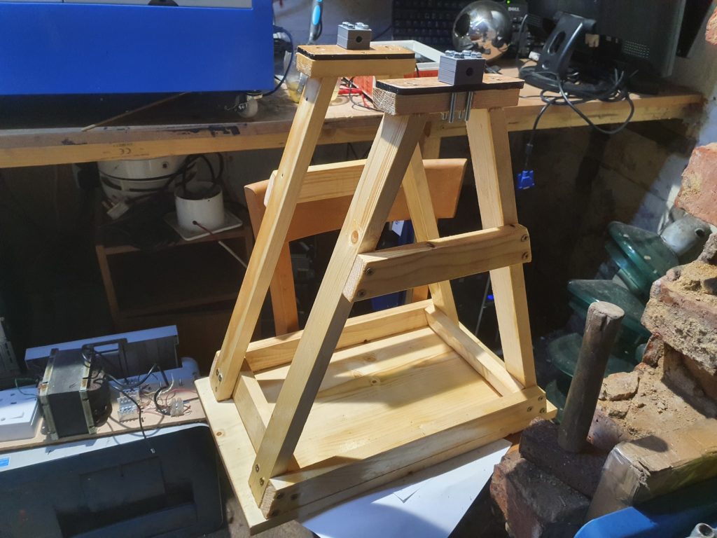
The disk support was made from 19mm x 40mm timber and screwed onto a 20mm thick base
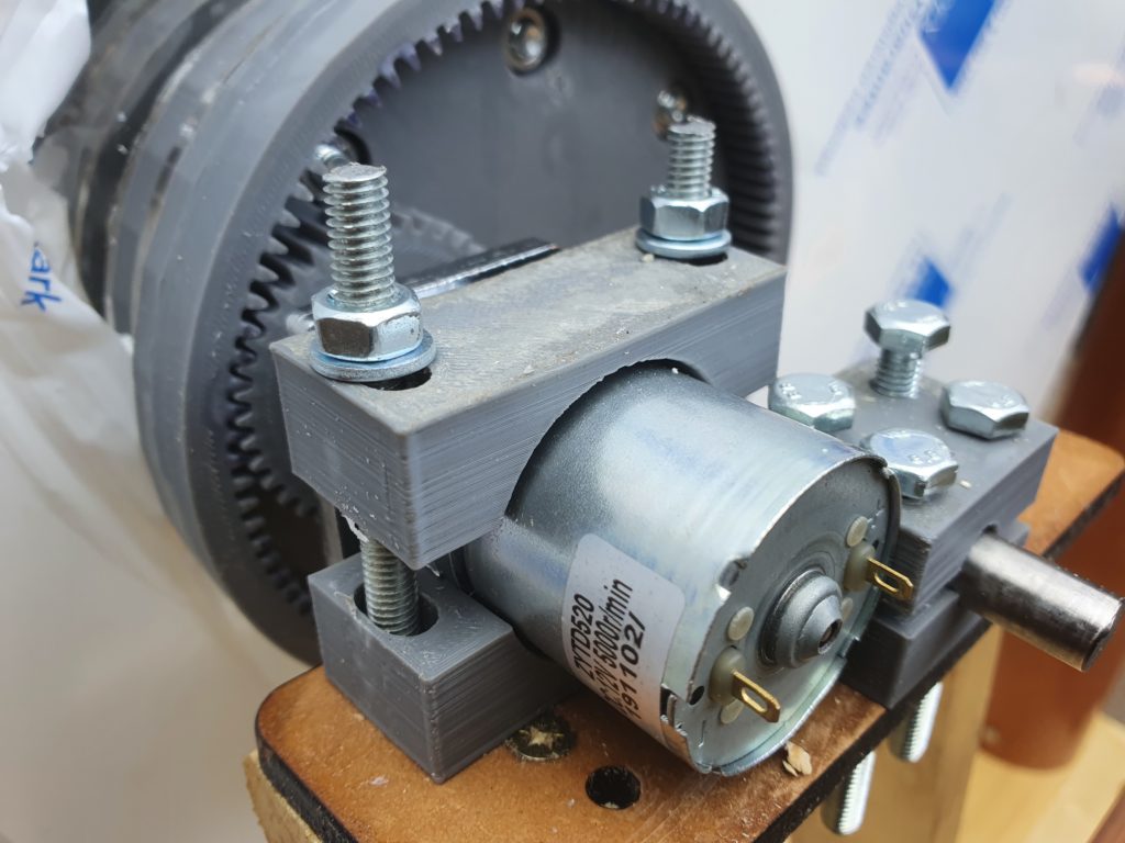
The motors and the central axle were clamped to this using a variety of 3d printed pieces. The motors drive the internal boss cog with a 3D printed gear at slightly faster than 60RPM (at 12v)
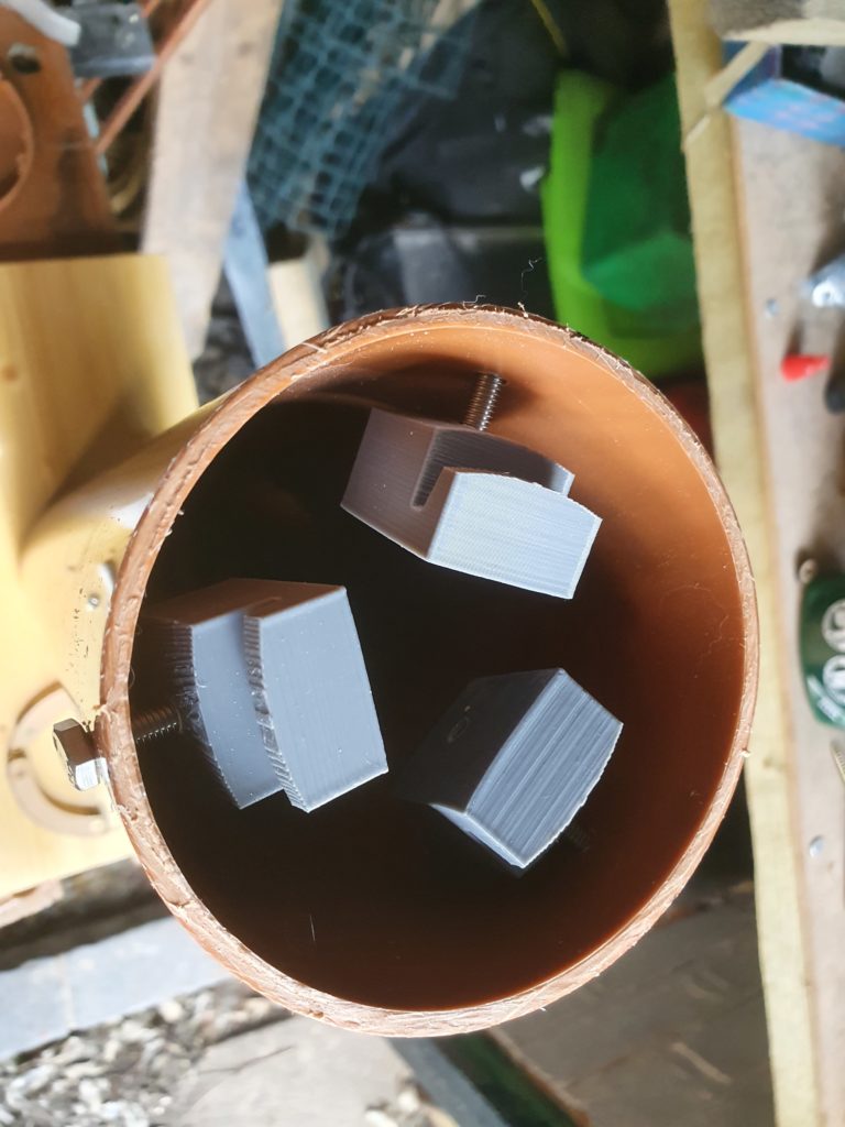
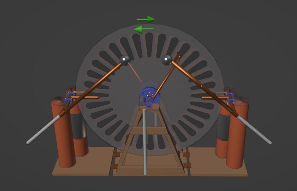
The stands for the charge collectors need to be much better insulated than wood would allow. So these are made from 100mm PVC piping
So the stand can be dismantles for storage the pipe is attached by 3 3d printed clips and a set of laser cut retainers. Screwed together with m6 bolts.
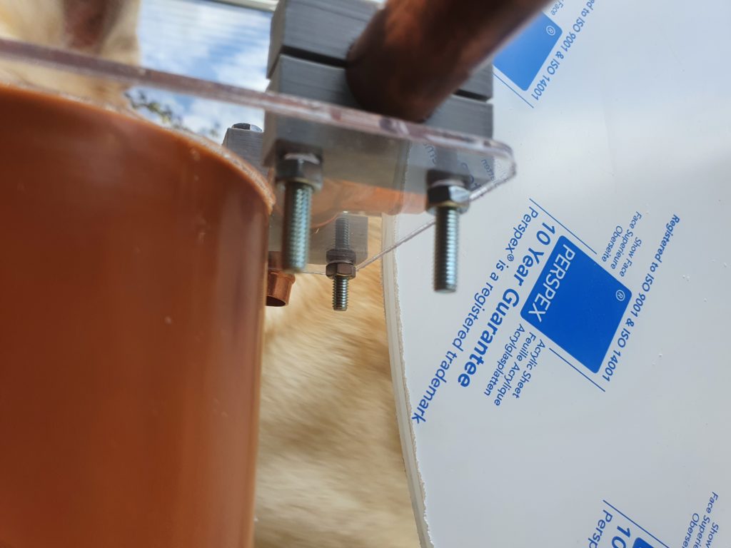
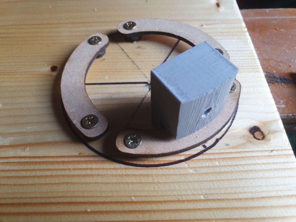
At the top of the tubes a laser cut piece of acrylic holds the charge collectors…
using another set of 3D printed bolt on clamps.
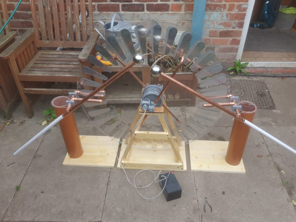
Trial setup showing disks, neutralisers, charge collectors, discharge wands and the wooden and PVC supports.
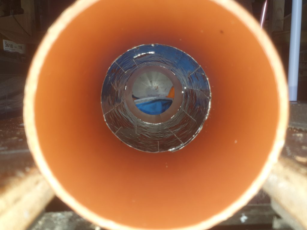
For longer sparks, we need some storage. Layden jars would be too big for the high voltages generated, So as I had some pipe left over I made layden tubes.
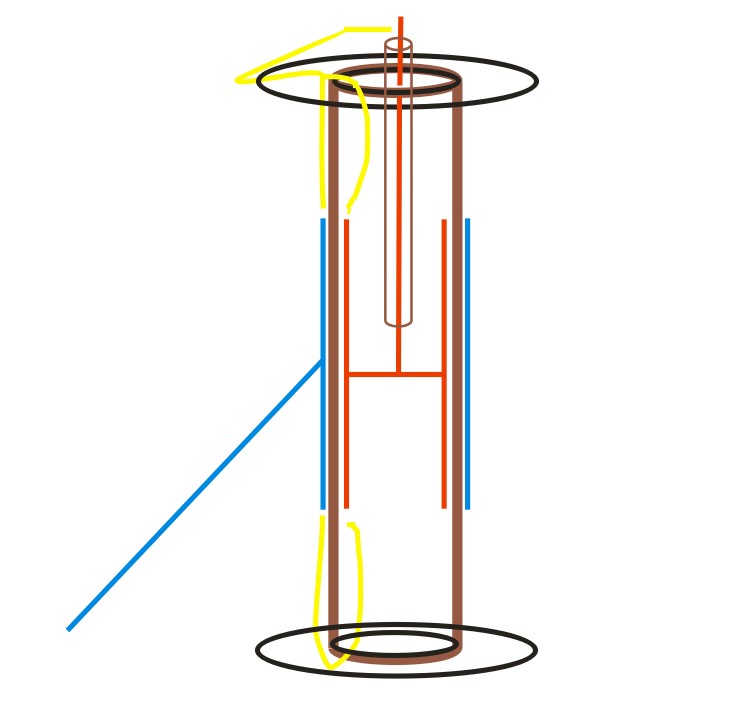
Each tube has 15mm between the electrodes and the top/bottom. This allows for roughly 250KV (with surface creapage) as long as the top and bottom have over sized ends.
Both the inside and the outside has 200mm of foil. Giving me 480pF of capacitance on each side. The two are in series so in operation 240pF but at over 900Kv
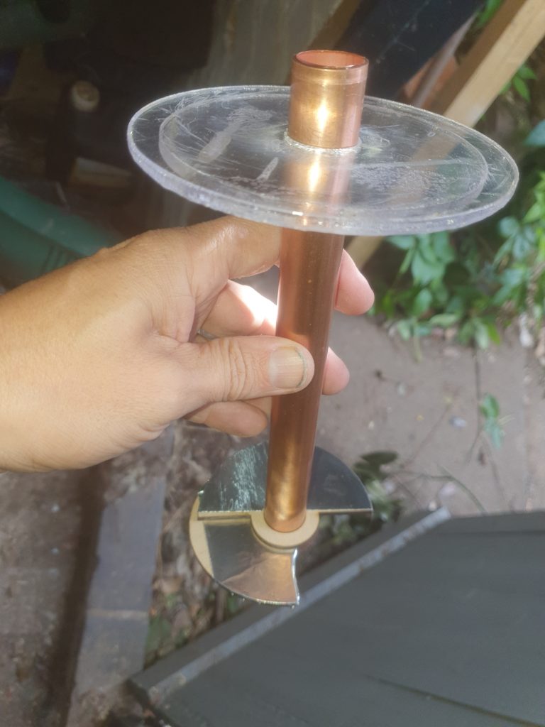
The inside foil is connected by a short length of 22mm pipe. and an “expanding” disk to connect to the inner foil.
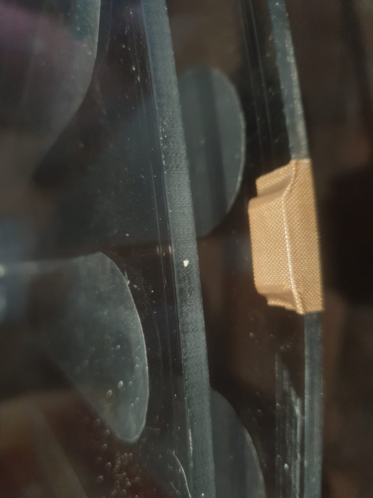
When running I found the disks are STRONGLY attracted to each other, and this was enough to stop the motors. So I’m using a 8 separators on one disk to keep the disks 3mm apart. this is made of a filed acrylic D shaped section, covered with PVC tape. At some time I’ll make a more permanent fix.