
Circuit diagram

Boards

The boards are a shared project on OSH park.
![]()
Software
Software and programming Details are here
BOM
1x 1uF Ceramic Capacitor
1 x LIR2023 rechargeable 3.2V lithium button cell
1 x 20mm Button battery holder vertical
2 x QRE1114 (or QRE1113) IR proximity Detectors
2 x 8mm Disk Vibration Motors
2 x 1K 0.25W resistor
2 x 10K 0.25W resistor
2 x BC337 Transistor
2 x micro on/off switch
2 x small tooth brushes (you can cut these down so 2 tooth brushes can make 3 bugs)
1 x 8mm plastic bead
1 x 8pin DIP turned pin low level socket.
1 x PIC12F510 8pin DIP processor. (PIC12F508/PIC12F509 will work with some minor changes)
Total Cost ~ £5.50 each
This project uses Lithium Button batteries, please note the warnings here – Do Not short out the batteries, and Do Not swallow them.
Construction.
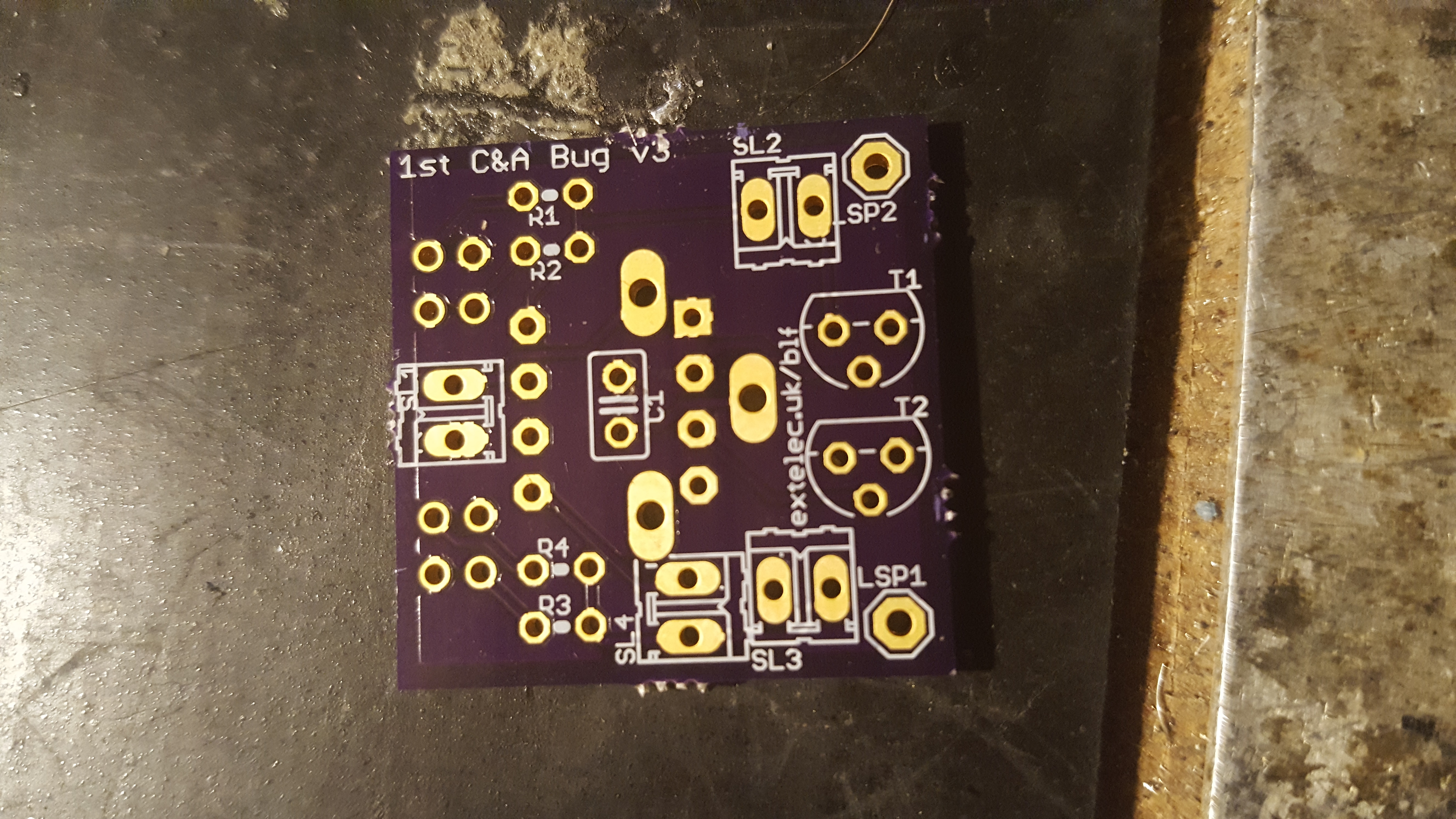 |
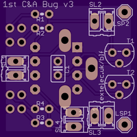
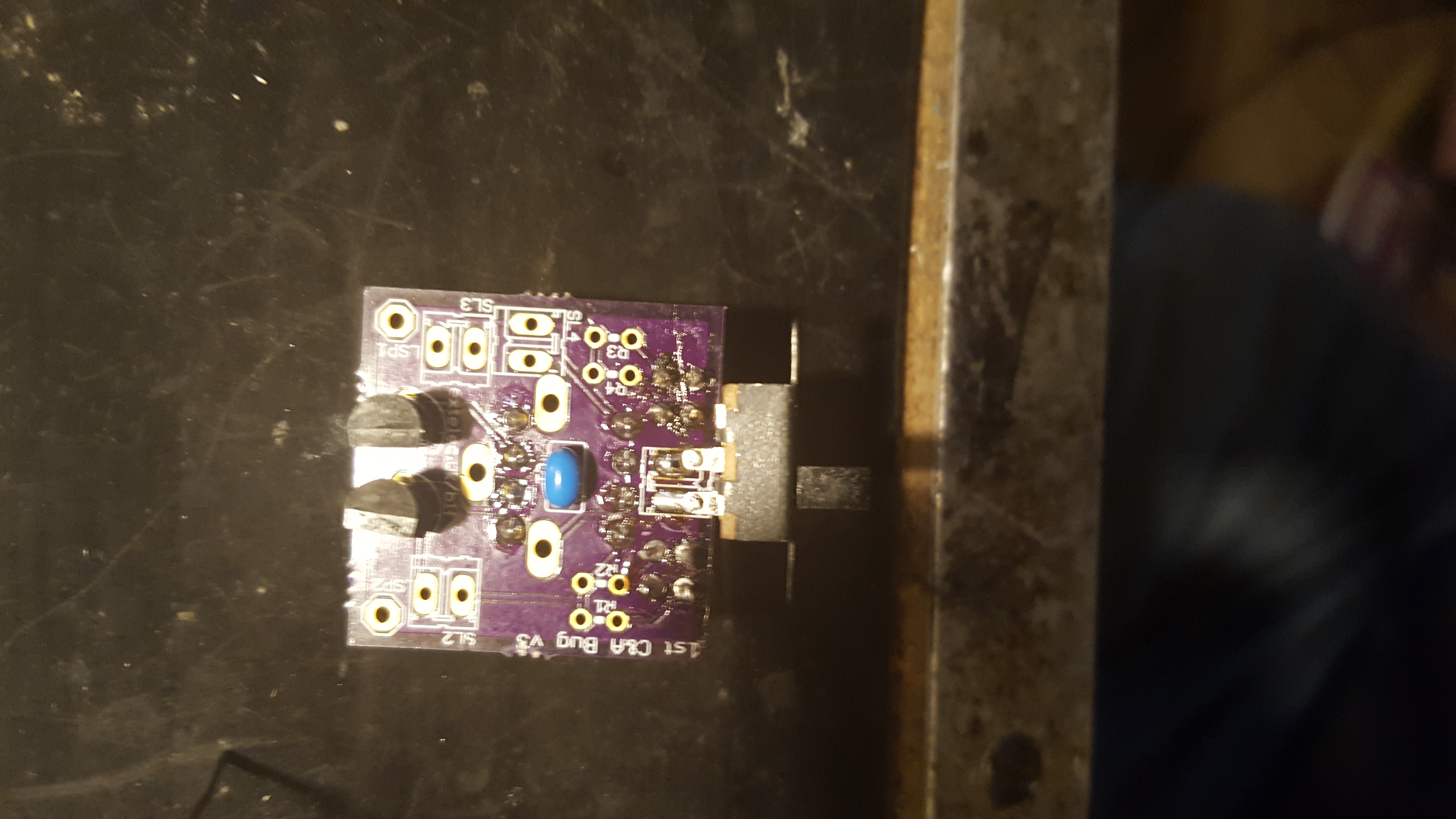
This is the TOP of the BLF PCB |
 |
Add in the small blue tantalum capacitor and solder on the other side, cut off the spare wires close to the board. |
 |
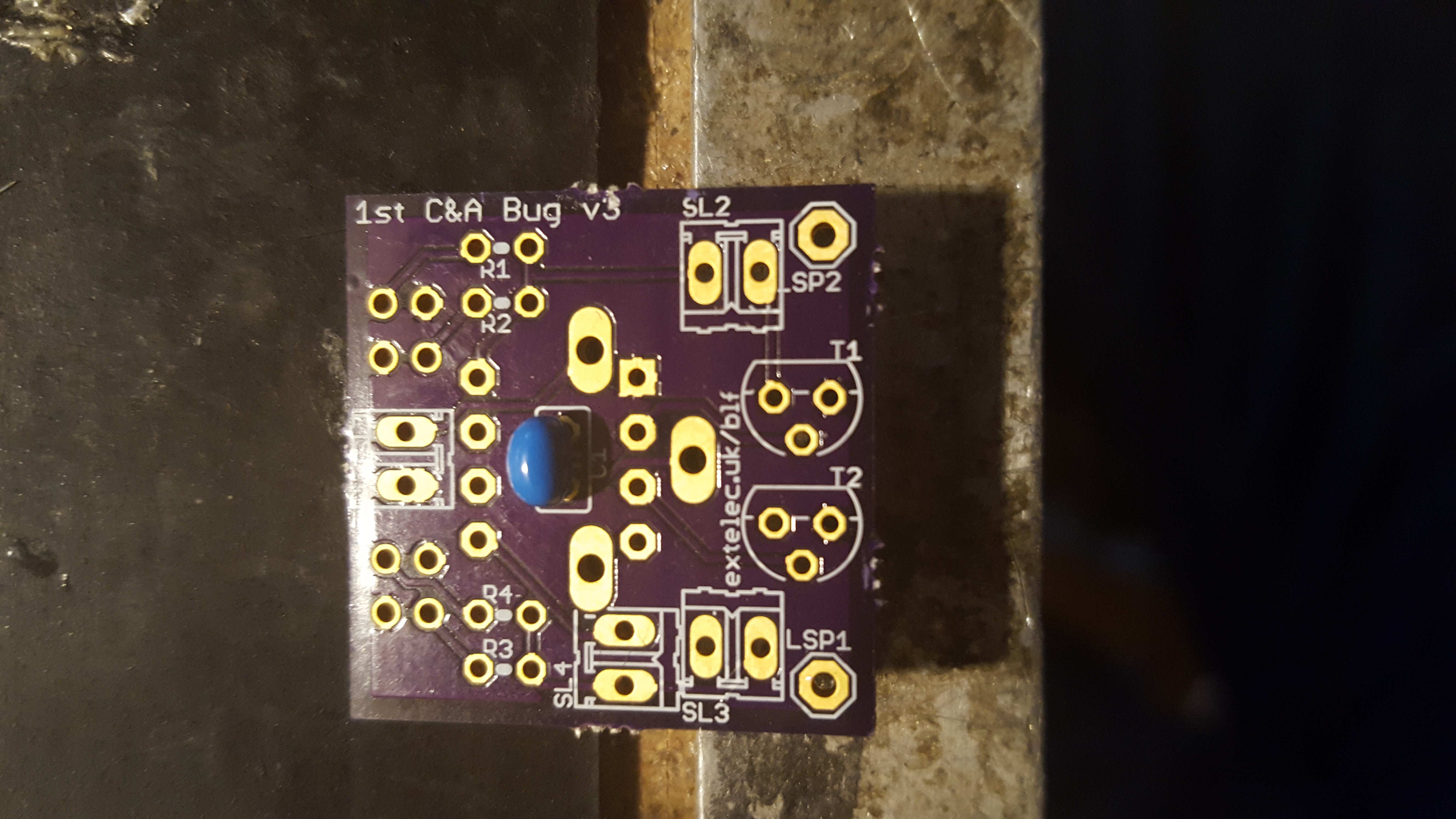
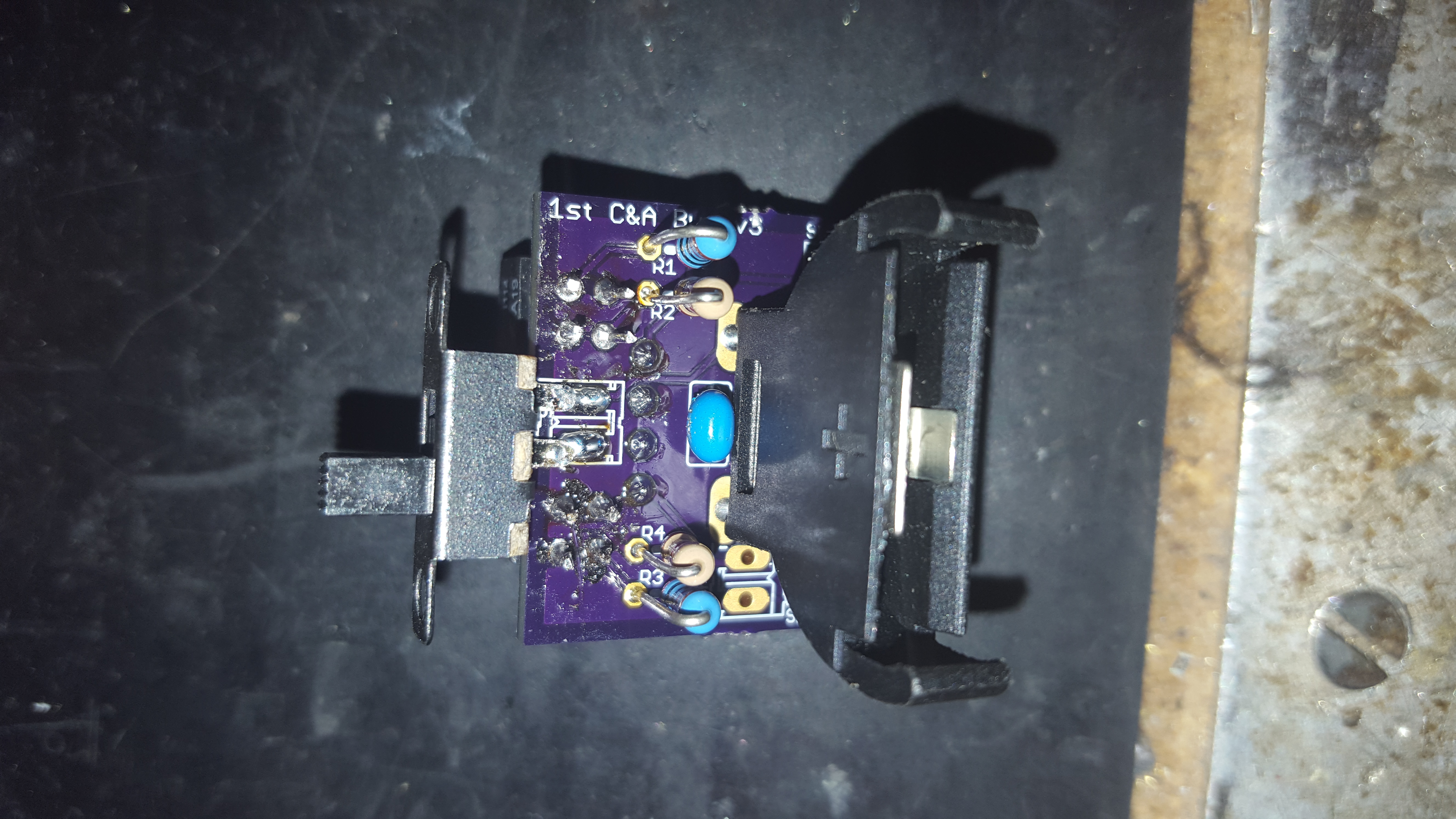
Turn the board over This is the BOTTOM of the BLF PCB |
 |
Insert and solder (on the other side) the 8 way DIP socket, Ensure the small D cut out in one end of the socket, matches the one printed on the board. Ensure there are no blobs of solder connecting the pins. |
    |
Insert the two infra-red sensors into the board. Before soldering Make sure that the small dot on each sensor is towards the middle of the board. Ensure that the LEDs in the sensor are both flush to the plastic housing and don’t stand proud. (If they do gently push them back in) Also make sure that the sensors stand straight up from the board and are at the same height from the board. The bottom of each sensor should be at the same height as the top of the IC socket. When all is straight and at the right height, carefully solder them in place. If these aren’t at the same height and straight, your bug won’t function correctly. |
 |
Solder in the two transistors flush to the PCB. cut off the excess wire on the solder side. Ensure there are no blobs of solder linking the legs of the two transistors. |
   |
Cut off one of the outer legs of the switch (as shown) and solder the remaining two legs into place flat and sideways on to the PCB |
   |
Solder in the inner two 1K resistors These will have a colour code of either Brown, Black, Red or Brown, Black, Black, Brown |
  |
Solder in the outer two 10K resistors These will have a colour code of either Brown, Black, Orange or Brown, Black, Black, Red |
  |
Insert the Battery holder flush to the PCB, you may have to bend the Capacitor a little towards the switch to get the bottom of the holder to sit flat to the PCB. Solder it in place on the bottom of the PCB being careful not to melt the IC socket. |
  |
Glue the red bead in between the two sensors. It needs to sit proud of the sensors by 1.5-2mm, you may need to file a couple of flats on either side to ensure it fits snugly between the sensors without bending them. |
 |
Insert the Microprocessor. Ensure that all of the legs have gone into their sockets. and that the D cut out matches the D cutout In the socket below. If the legs are too wide to fit into the socket carefully push each side inline against a table top. Don’t try to move them one by one. |
  |
Taking the two tooth brush heads roughen the tops sandpaper and glue on to the PCB Ensure that both heads are flat and leave to dry |
 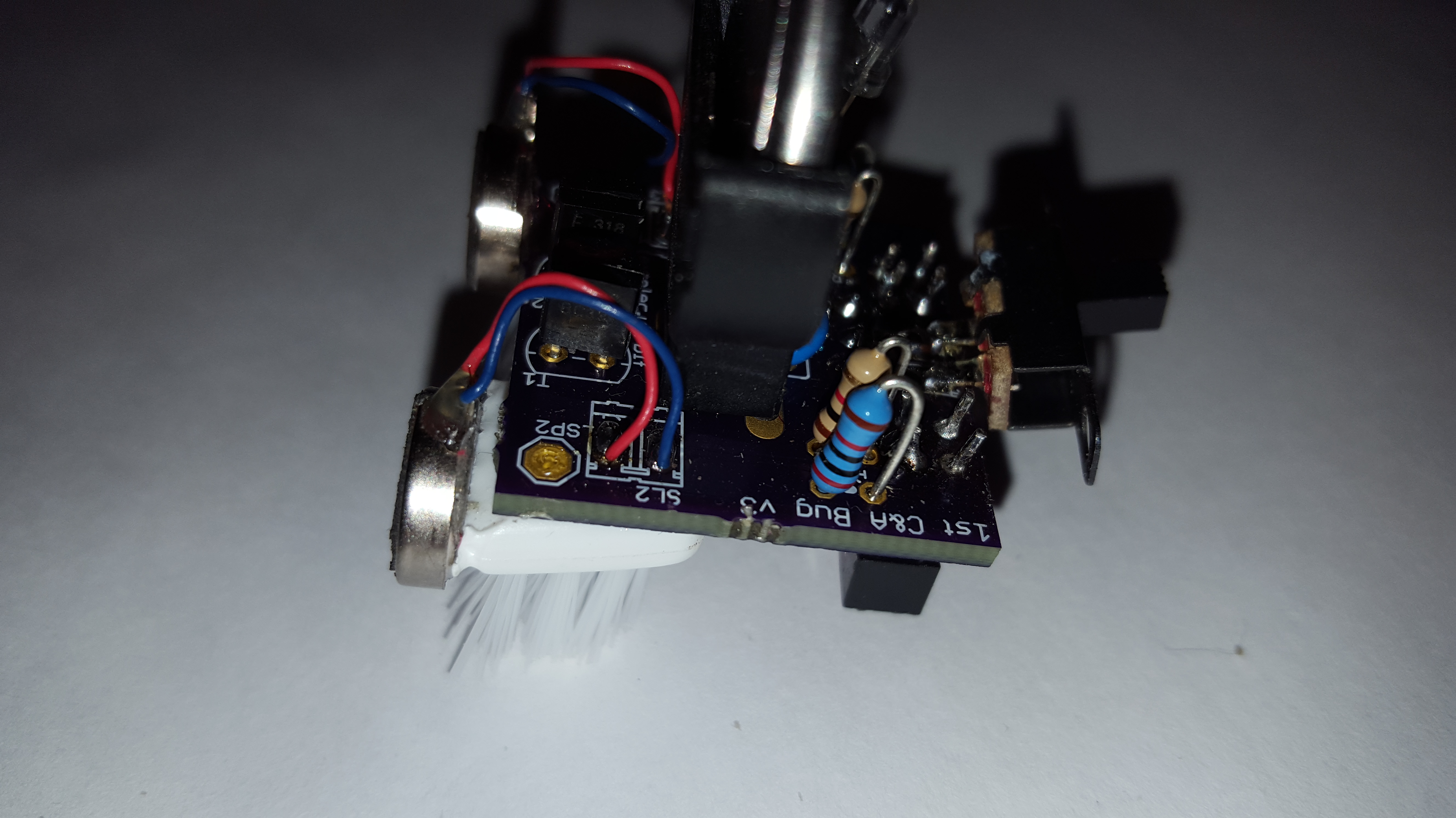 |
With the two vibration motors, solder the leads on to the top of the board only. Un-peal the backing paper from the vibration motors and stick them to the flat plastic end of the tooth brush head.(not on to the bristles) If you are happy with the position I suggest using a stronger glue to better affix the motors.
|
 |
Make sure the switch is OFF It should be towards the cut off leg |
 |
Insert the battery, MAKE SURE THE + on the BATTERY is the same side as the + ON THE HOLDER |
 |
Repeatedly stroke the bristles of the brushes towards the back of the bug. After a while they will stay at a slight angle pointing backwards. Do this on both sides of the bug. |
| Continued in Running the BLF | |
| Debug LED
An LED can be soldered on to the spare pads (PL4) with a suitable series resistor. The LED has the following cadences . – . – Right |