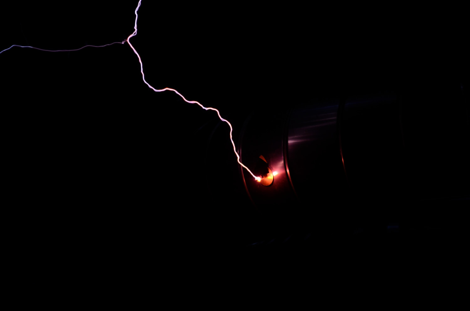
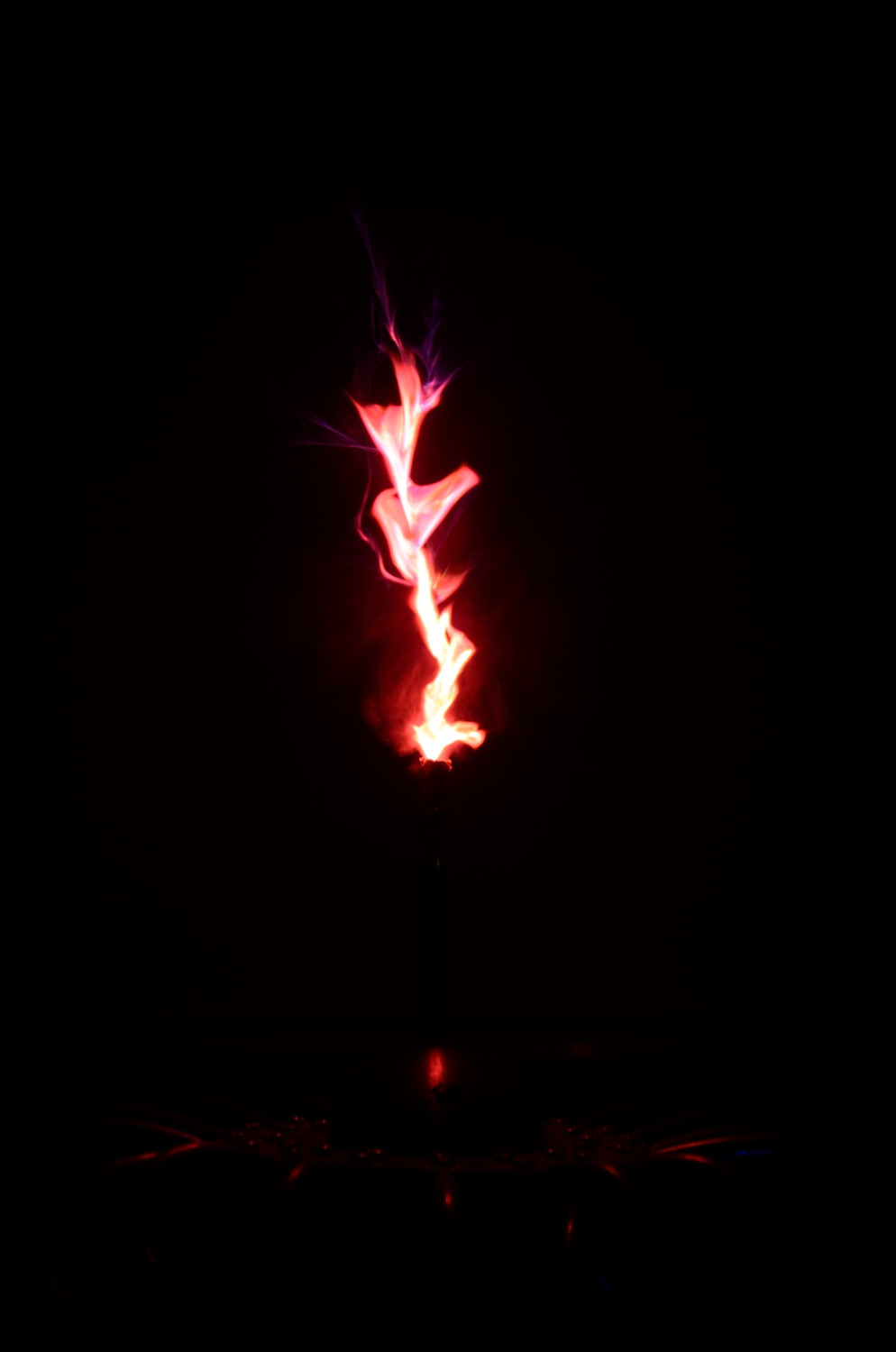
A test of breakout points made almost entirely of Strontium. The idea is that rather than containing the Strontium in a tube that needs to withstand the heat of an arc, we make a breakout with as much Strontium as possible. Of course Strontium is quite a good insulator so we need to add in a conductive component and something to hold it all together. This test uses PVC glue as the binder and bear conductive ink as the conductor.
Initial tests on a large rotary classic tesla coil
Some effect, but not as strong as Id hoped. Although the one on the chicken stick wasn’t bad.
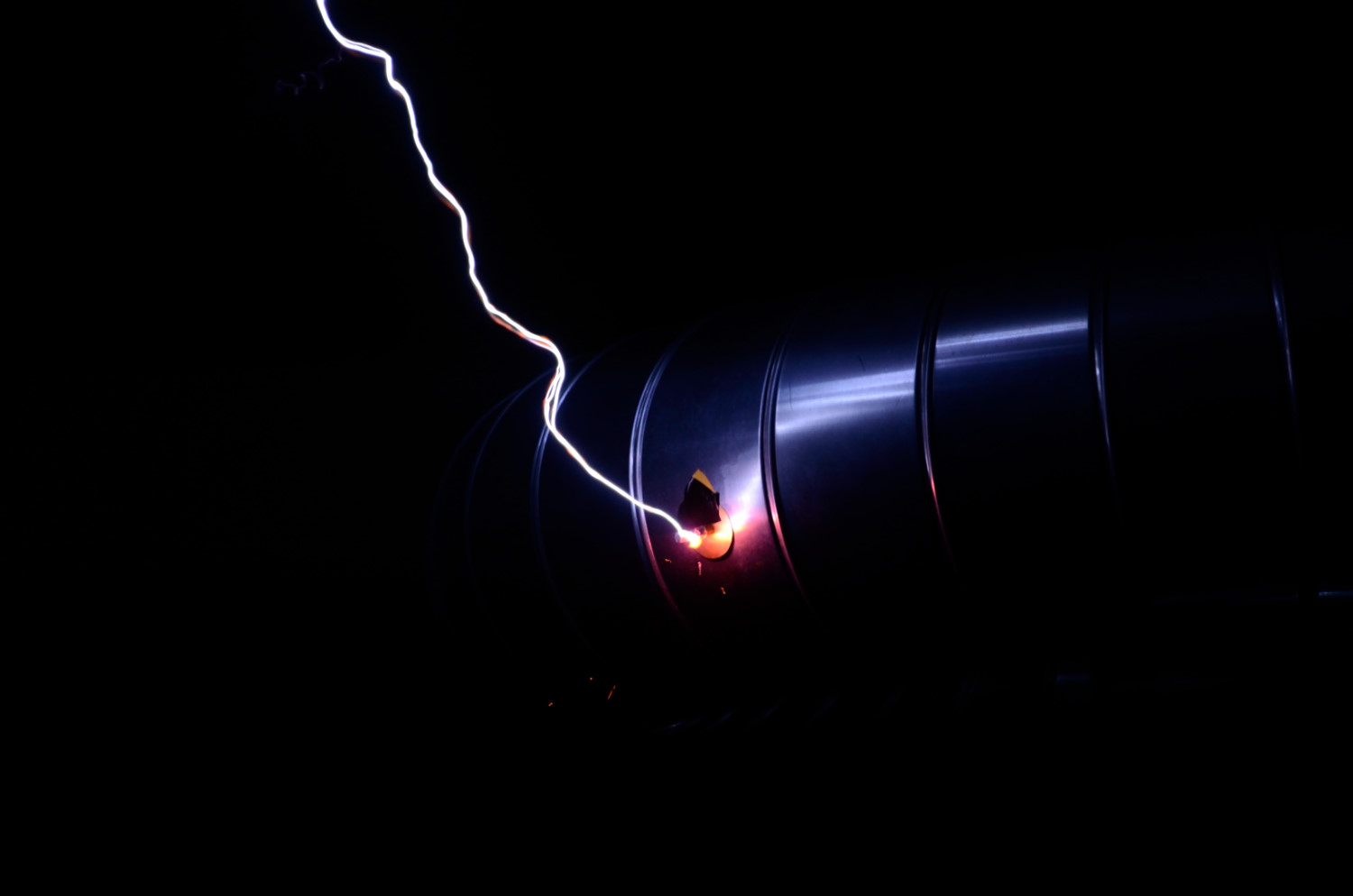
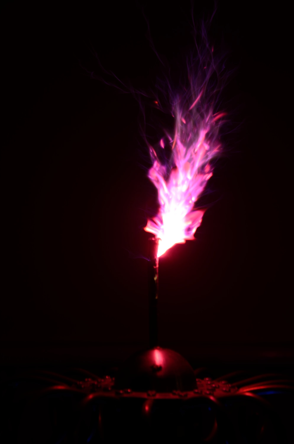
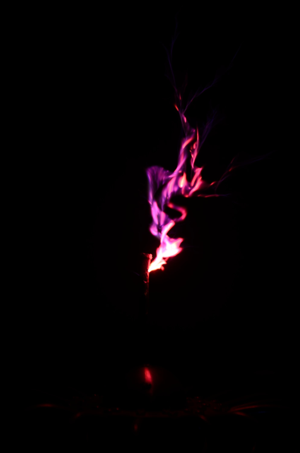
SSTC 1Kw Much better results.
A great improvement on any other methods that I have used, and better still, the breakouts seem to be quite resilient and can be used multiple times.
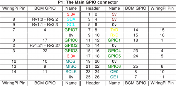
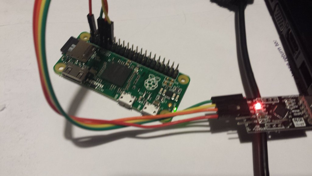
Install into a sd card and make sure it runs (green light at least)
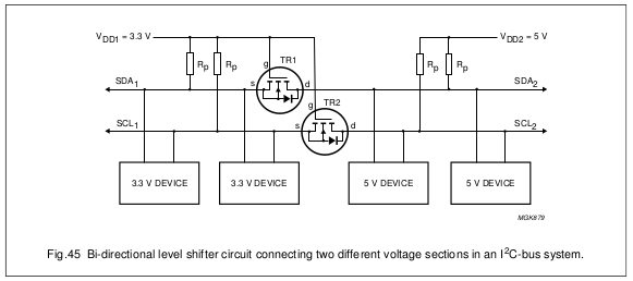
With a 3.3v RS232 adapter connect earth and RX/TX to your PI. Be careful some adapters are only 5V and will damage your PI’s UART pins.
Setup your PC (I use Tera Term) serial adapter for 115200, 7 bits, even parity, 1 stop bit.
Boot your PI
If you get a screen of gobbledegook then good, otherwise swap your TX and RX around. When the gobbledegook has finished, press return a couple of times, and you should get a login prompt.
For some reason the console and boot up output at different baud rates (Caused by auto baud rate detect, settings above amended so this shouldn’t happen now)
Configure your PI the usual way. You will need some network to get your updates, but apart from that you have a working PI.
If you are brave (or idle) you can connect the +5v line from your serial adapter to power your PI too so you don’t need another usb power lead. Just be very careful that you attach it to the correct pins, otherwise your PI will be damaged.
Useful links.
(although I found the baud rate setting wrong everywhere I looked. Either auto baud rate detect at work, or it changes from distro to distro)
The baud rate is auto detected, the native speed is 115200 (amended above) The auto detection only happens at the login prompt. The auto detection won’t pick up changes in bits/stop bits/ or parity. You can change the console getty port/speed/parity settings look at RPi serial connection above.
WiFi
If you have a wifi adapter and micro USB to USB lead, you can connect to WIFI. After connecting via RS232 edit the file /etc/wpa_supplicant/wpa_supplicant.conf using sudo nano
add in the lines
network={
    ssid="Your_WIFI_SSID"
    psk="Your_wifi_password"
}

and reboot the pi sudo shutdown -r

re log in to the pi and type ifconfig to fins the wifi IP address.
Then you can ssh to your PI and even better update the software.
It is often said to me that a Tesla Coil produces 1,000,000 V or more.
This is a common misconception. Unless you have an absolutely huge Tesla coil, the actual voltage at the top load is much smaller.
The mistake comes from the widely accepted rule of thumb that the voltage that an electrical discharge will jump determines the voltage present, in normal air at atmospheric pressure this equates to 30Kv per cm . [Paschen’s Law] So it is easy to see that if a tesla coil produces sparks that will jump 30 cm or so, this means that the voltage on the top load must be roughly 1MV.
Unfortunately the situation on a tesla coils top load is a bit more complicated and the 30KV/cm rule does not apply in quite the same way.
The physics of the arc itself needs to be taken into account and the Radio frequency AC that is created. The Tesla coil is effectively a high voltage, high impedance AC current source [Tesla Coil – Output voltage] . So when the spark is being created as the spark grows it forms a capacitor that draws current from the tesla coil reducing the top load voltage. This effect happens as soon as the torroid breakdown voltage has occurred and gets progressively worse as the spark leader forms. This is therefore governed by the voltage breakdown of the minor diameter of the tesla coils top load
The maximal achievable potential is approximately equal to the sphere radius R multiplied by the electric field Emax at which corona discharges begin to form within the surrounding gas. For air at STP the breakdown field is about 30 kV/cm – [https://en.wikipedia.org/wiki/Van_de_Graaff_generator]
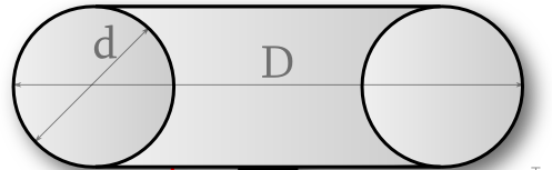
So the voltage on the top load of a tesla coil tends to be slightly more than the standoff voltage of it smallest diameter. Vmax = R·Emax (R = Radius, Emax = Breakdown voltage in air 30Kv). For a teslacoil with a 20cm (minor) diameter top load this is around (20cm/2) * 30Kv = 300Kv
The minor diameter is d
But… 300Kv will only give sparks of 10cm according to the 30Kv/cm rule, Tesla coils can easily achieve better than that?
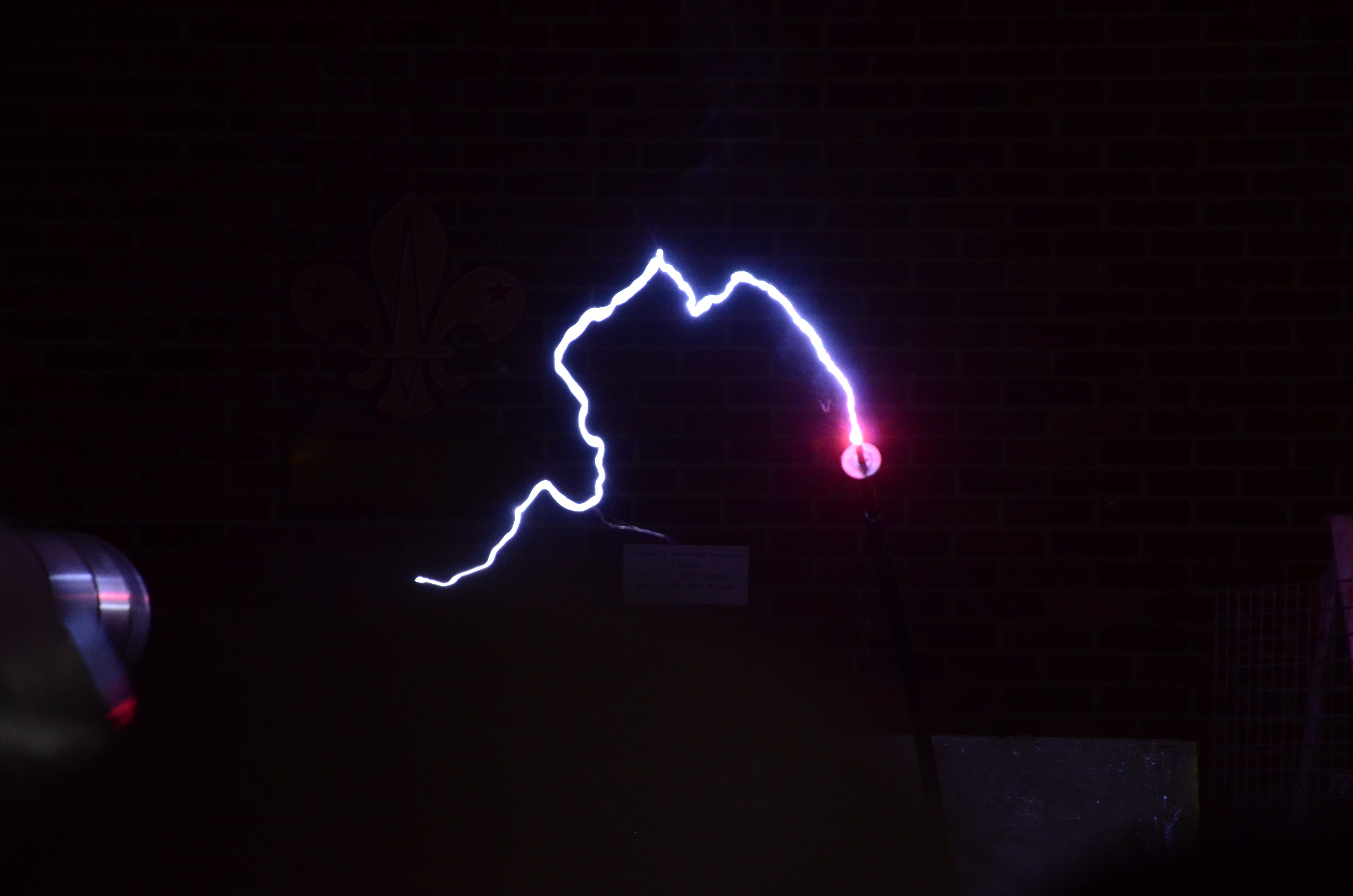
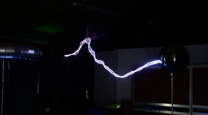
This is where the second aspect of the tesla coils output comes in to play. The voltage on the top load is both AC and Pulsed. Each burst or pulse of Radio Frequency (RF) creates a 10cm long (using the example above) arc leader from the available 300Kv. This heats and ionizes the air, making it conductive this is what you see as the arc in the air.
If very rapidly after the first burst of RF comes another, the channel won’t have had time to dissipate so there is a conductive channel the new pulse can use. The energy rushes to the end of this ionized channel and tries to create another 10cm leader there. Not only does this almost double the spark length, but the energy also re-ionizes the channel. This continues with the third, fourth, n … pulses, each time adding on a slightly diminishing (due to losses) leader to the existing spark.
This continues until something disrupts the channel usually the air rising as it get hot.
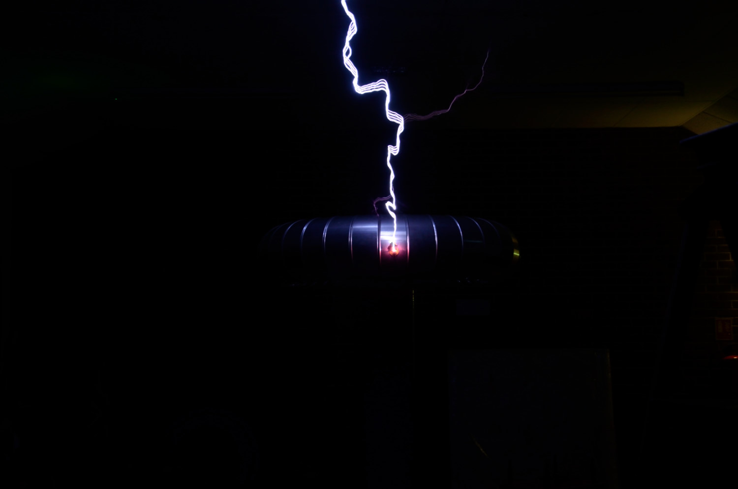
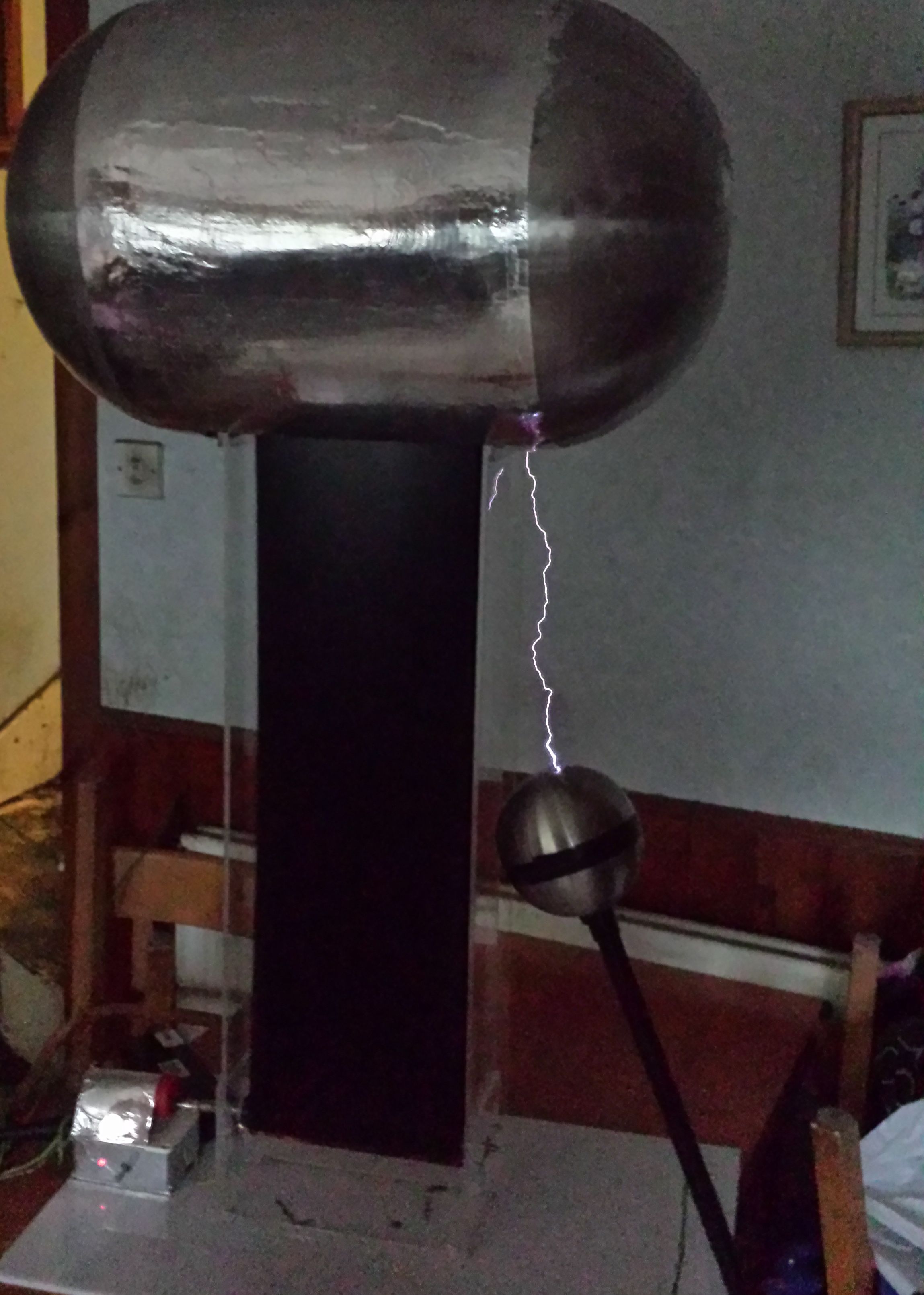
This can be easily proved with a modern electronic tesla coil. Set the coil to produce a single burst of RF, this gives a discharge that can be measured using the 30Kv/cm rule and can give a fairly accurate indication of the terminal voltage.
So unless you see a tesla coil with a 66cm minor diameter top load it isn’t producing 1MV
The BIGG coil of Oklahoma, probably the only true 1MV tesla coil.
Yes, I know, its was taught to you at school. Me too. I even have a book that has separate chapters of static electricity and conventional current electricity. So what is the problem, well it took me years to work out that there is no such distinction. Its all electricity. Static electricity on the terminal of a VDG sphere doesn’t suddenly transform in to current electricity when it is discharged and current electricity doesn’t transform into static when its stored in a capacitor.. The same rules must apply to both.
To use the water analogy, water is the same if its in a lake or in a stream.
I’m my mind I can’t think of any situation where static electricity exists. Capacitors, Van de graph terminals (also capacitors) all store charge. But non are static, there is always leakage current. To charge these devices there must be current.
So is its not static electricity, its stored electricity (charge) or conventional electricity(current) , both or just electricity.
Reading Physics books there appears to be a whole set of laws that govern each “type” of electricity, but in reality the effects are always there. One of the problems is that ‘static’ electricity is generally taught with high DC voltages, current electricity is taught with low DC voltages. The effects you see are dominated by the voltage, for example.
Electrical attraction occurs in all capacitors. But at high voltage the effects are much larger and so easier to see.
Resistive heating has a larger effect at low voltages, but is harder to see at high voltages (which is why transmission lines are high voltages)
The more you work on high voltage, or with high frequency electricity the more these effects become apparent.
So banish ‘static’ as a description and replace with high or low voltage, charge or current this is really what is going on.
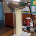
After a lot of work, I just managed to get everything to Notts Gaussfest. This was really the first time all of the pieces had run together for any length of time.
I found a number of issues. The belt stuck together at high charges, usually stopping the belt completely and the motor control would crash when there was a really good discharge.
The motor problem was a partially solved by coating the controller in aluminium foil, which at least let me run the VDG for the day at Notts Gaussfest.
First light tonight 6″ sparks, not bad for the first time I’ve powered it up.
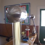
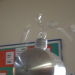
At the moment the limiting factors to the spark length/voltage is the unfinished top load and a problem with the belt. The top load has a very uneven surface, I believe I’m losing charge this way.
When the VDG starts charging the two sides of the belt are attracted to each other and they rub together, reducing the charging. I tried tightening the belt with no effect, so I have ordered 0.4mm (was 0.25mm) latex to make another thicker belt.
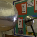
After changing the charging belt to 1mm pure rubber I finally achieved the full 1MV
350mm spark @3kv/mm that means a total voltage of 1050KV (1.05MV)
At full out the motor is really working hard and gets very hot, so I suspect I can get more out of the VDG with another motor.
Tesla Coils and High Voltage
We use cookies to ensure that we give you the best experience on our website. If you continue to use this site we will assume that you are happy with it.