Signetics – Fully Encoded 9046 x N, Random Access Write – Only – Memory
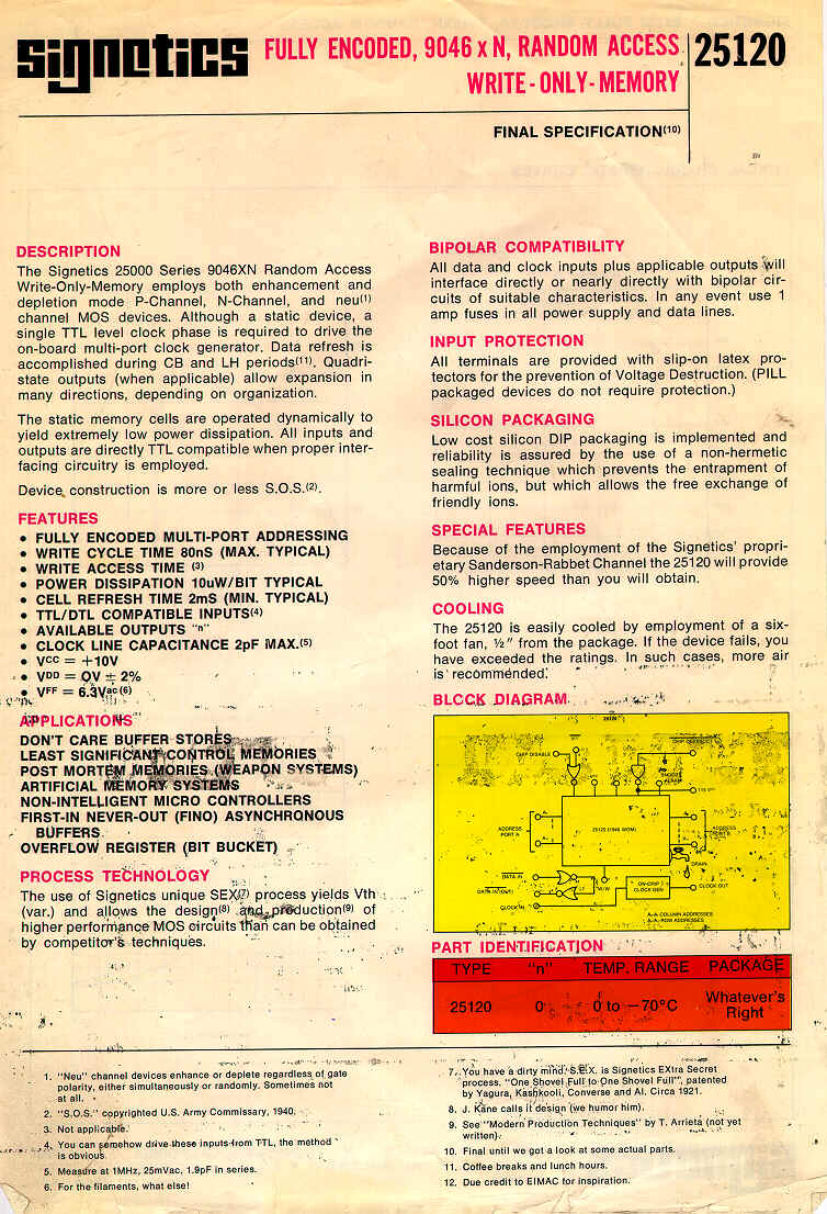
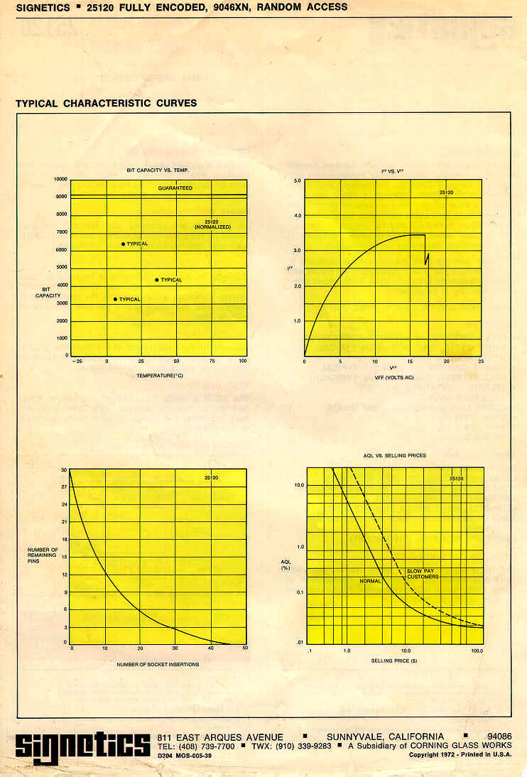
Released in the Early 70’s For some reason the IC didn’t take off. Although I can think of a number of machines that must have used these devices.

Signetics – Fully Encoded 9046 x N, Random Access Write – Only – Memory
Released in the Early 70’s For some reason the IC didn’t take off. Although I can think of a number of machines that must have used these devices.
Edit /etc/network/interfaces
Change
[code]iface eth0 inet dhcp
to
iface eth0 inet static
and below enter
address 192.168.100.1
netmask 255.255.255.0
network 192.168.100.0
broadcast 192.168.100.255
gateway 192.168.100.254
So I bought a Minimus32 Development board from [shortlink url=”http://www.modtraders.co.uk/minimus-32-avr-usb-development-board.html” title=”Mod Traders”]
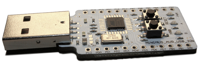
Couple of reasons for the purchase, Its was cheap, and it had a small processor and USB support out of the box.
OK, 1 and 2 are true, 3 is a little more complex.
After trawling the internet All I found was out of date information, information on the original Minimus board, or information using an old version of Atmels IDE. Having struggled in the past with old IDE’s I decided to use the newest one and brave it out.
So, For Windows…
You can download Atmel’s latest IDE free from here [shortlink url=”http://www.atmel.com/microsite/atmel_studio6/” title=”http://www.atmel.com/microsite/atmel_studio6/”] It is a Visual Studio based IDE and looks pretty good. Unfortunately there is no support for the bootloader contained in the minimus32 board.
So to get a hex image onto the Minimus 32 you need Flip downloadable for free here [shortlink url=”http://tinyurl.com/7jqeg3l” title=”http://www.atmel.com/tools/FLIP.aspx”]
Braving the new environment I cut and pasted a demo code sample (blink )
[code]#include <avr/io.h>
#define F_CPU 16.000E6
#include <util/delay.h>
#include <avr/wdt.h>
void init_ports(void)
{
PORTB = 0b00000000;
DDRB = 0b00000000;
PORTC = 0b00000000;
DDRC = 0b00000000;
PORTD = 0b00000000;
DDRD = 0b01100000; // Set LEDs as output
}
int main(void)
{
MCUSR &= ~(1 << WDRF);
wdt_disable();
init_ports();
while(1)
{
if (PIND & 0b10000000) {
PORTD = PORTD & ~0b01000000;
PORTD = PORTD | 0b00100000;
_delay_ms(200);
PORTD = PORTD & ~0b00100000;
PORTD = PORTD | 0b01000000;
_delay_ms(200);
} else {
PORTD = PORTD | 0b01100000;
}
}
}
I set the uP to ATMEGA32U2 hit build and It compiled first time.
Went into Flip, loaded the .hex file and sent it to the Minmus32. After a little playing with the buttons it ran.
(Tip: to put the Minimus into “Load” mode you need to press RESET, press HWB, release RESET and release HWB, just roll your finger over the buttons)
So a USB example.
I found that you can get the latest version of the LUFA libraries from here [shortlink url=”http://tinyurl.com/mx8flmo” title=”http://gallery.atmel.com/Products/Details/47ba24a4-d17b-4fed-b244-f5998b3d789d”] and the are already formatted for Studio 6
Loaded the Libraries and tried the demo project for USB to RS232
It compiled, but wouldn’t run.
Cutting a long story short there were a number of things wrong. The Processor speed was incorrect, the target board wasn’t set correctly and the LUFA libraries didn’t contain the code specific to the Minimus32 Board.
So. to fix these.
In Atmel Studio 6, Goto Project->Toolchain -> AVR/GNU C Compiler -> Symbols
Ensure they look like this
[code] F_CPU=16000000UL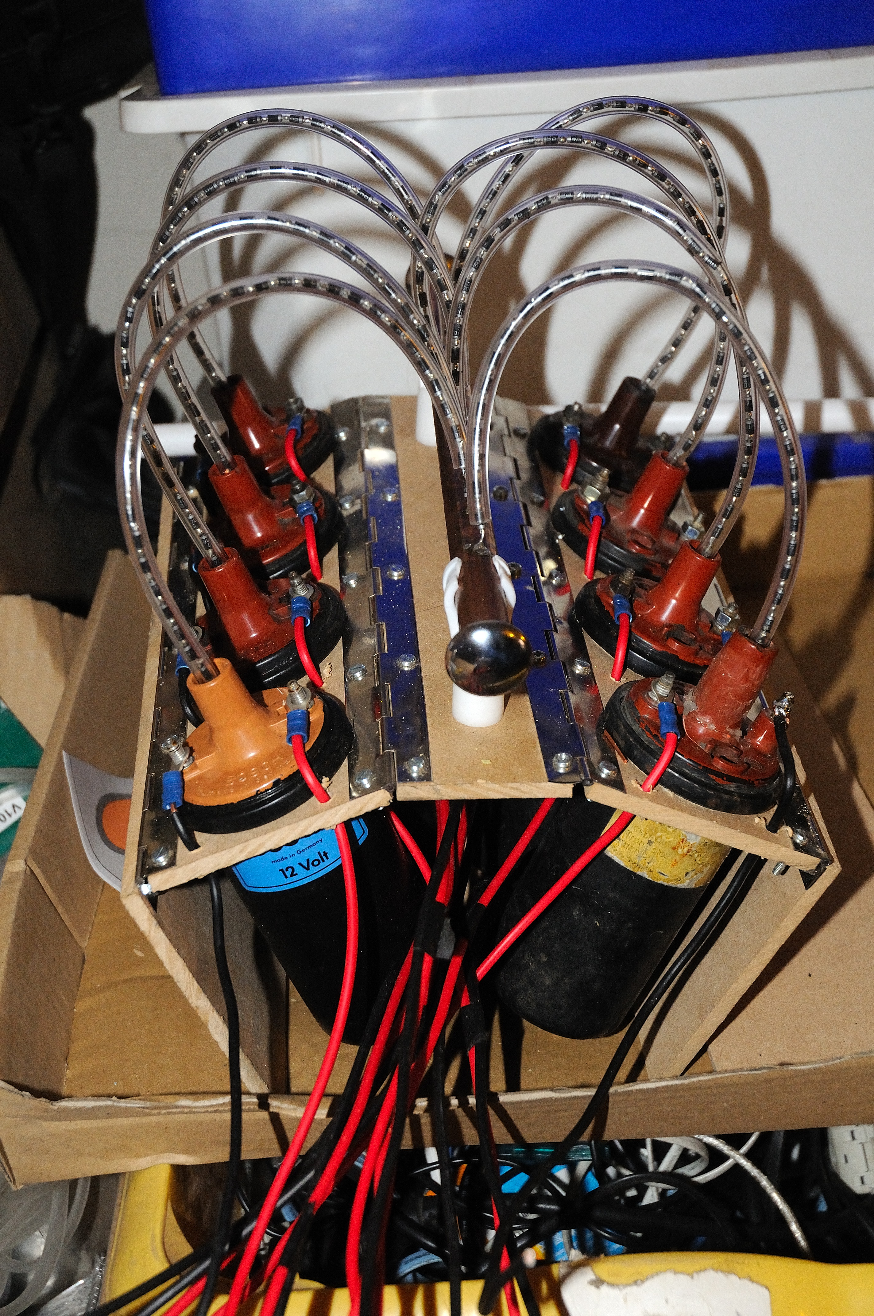 The V8 Ignition coils
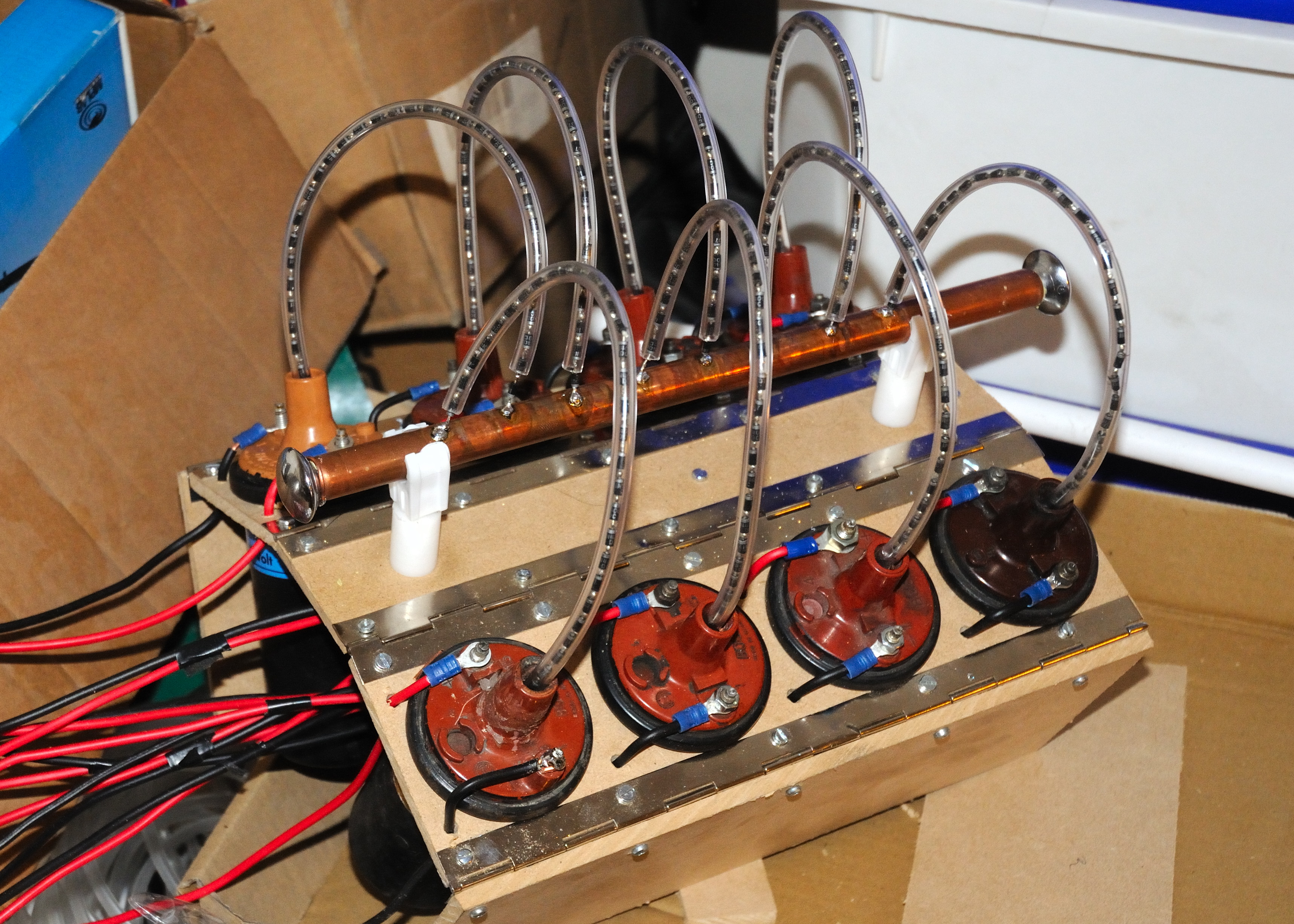 A 30 Kv power supply using 8 car ignition coils. The output of the coils are rectified with strings of 40 x 1n4007 diodes.
Each ignition coil, run flat out, draws around 5A at 12V so in theory the output should be around 300-350W drawing around 40A from the 12V supply.
The advantage of this drive is that there is no mains to back any fault, so it does make using the supply (slightly) safer than a mains powered unit.
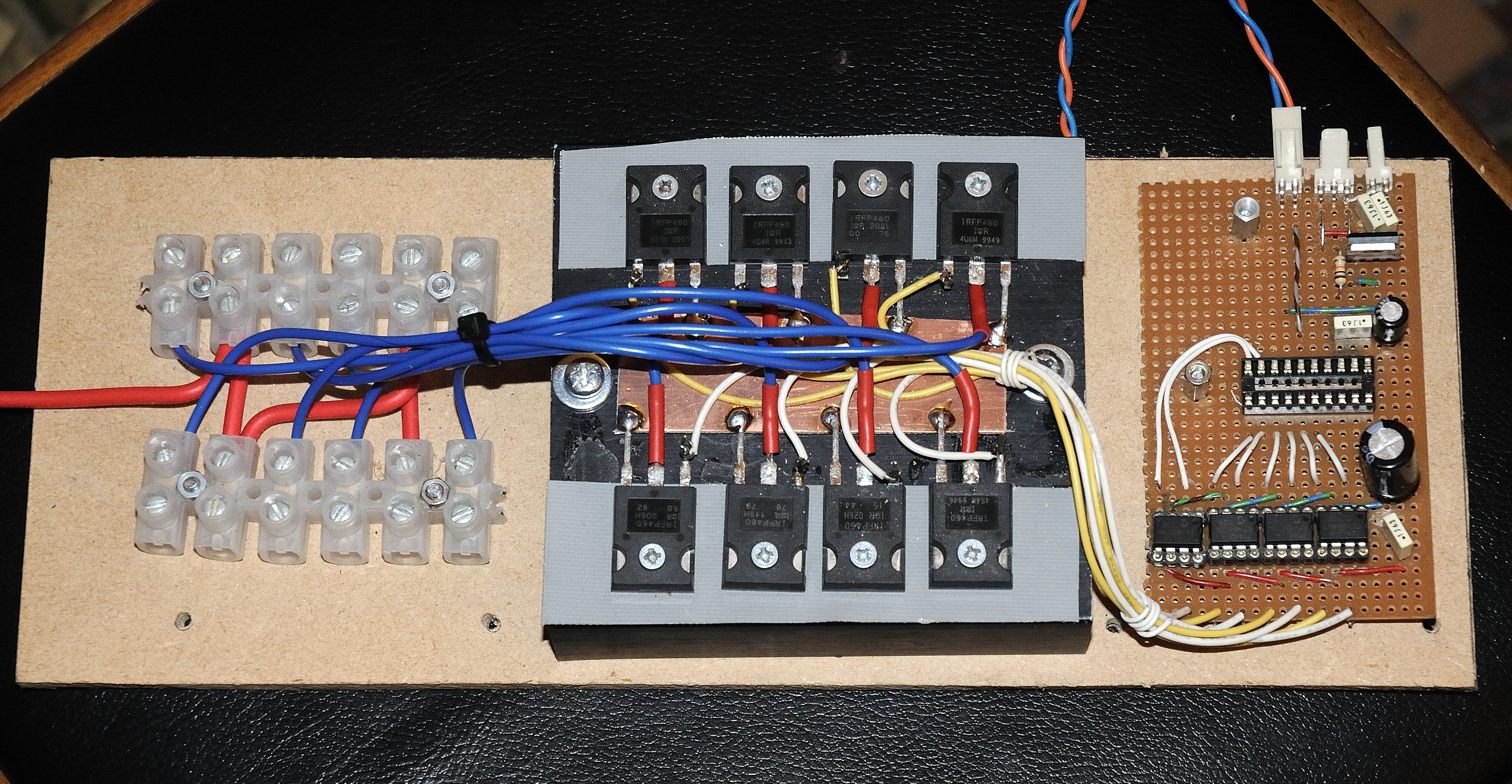
The ECU (Engine Control Unit)
The heart of the power supply is the ECU. The ECU gives some control of the output power of the system. The power is controlled by a variable resistor which controls the average power to the coils.
By arranging that no coils fire at exactly the same time as any of the others, the peak current draw from the batteries is limited, this allows smaller batteries to be used at lower powers. It also smooths the output so a smaller HV smoothing capacitor may be used. It effectively gives an 8 phase rectified HV supply.
To implement this there is a PIC18f14K50 controlling the timings of the 8 coils and taking control from a variable resistor. The PIC ensures that the on time of each coil is set to a maximum value ( 2.5mS for now can be as high as 3.5mS) so the coil will not be run into total saturation. It also spreads the pulses out over the 8 coils to prevent multiple coils turning on at the same time (except approaching full power where this is unavoidable.)
We have POWER!!! First test at full voltage 24v (2 x 12v SLA) into a jacobs ladder. Added 0.1uF caps across each of the coils to limit voltage rise when turned off. This is a much bigger problem at 24V than 12V. No clues at actual power. Well over 10A. My meter only goes up to 10A, and the fuse blows at 12A, I need a larger ammeter, and a new fuse. Continued in Strand on Tesla Coil
[shortlink url=”http://tinyurl.com/msd4o8v” title=”Continued From V8 Tesla Engine”]
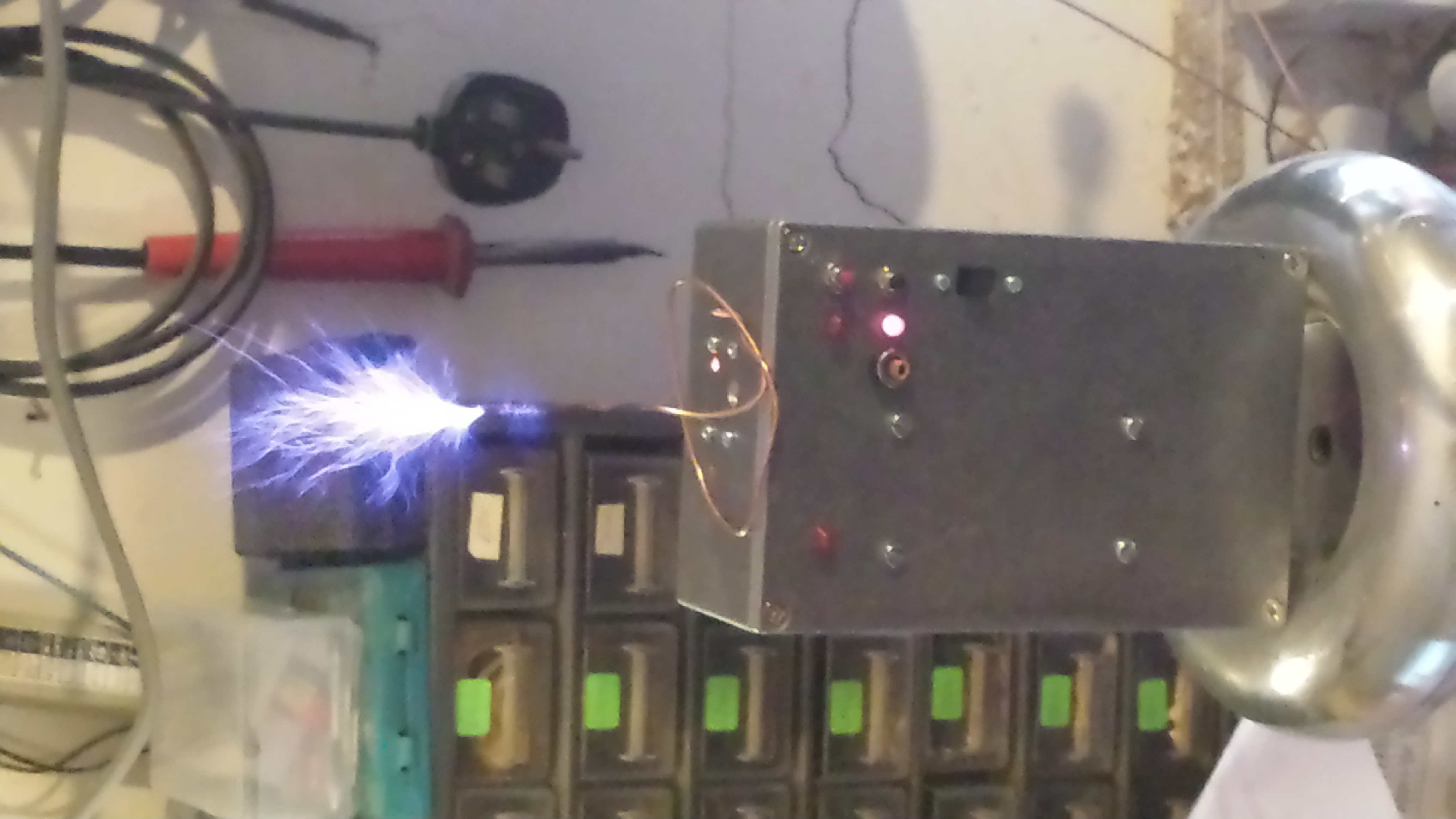
After playing with the V8 Tesla engine I realised that I could build a stand on tesla coil. The lack of mains power could make this “fairly” safe.
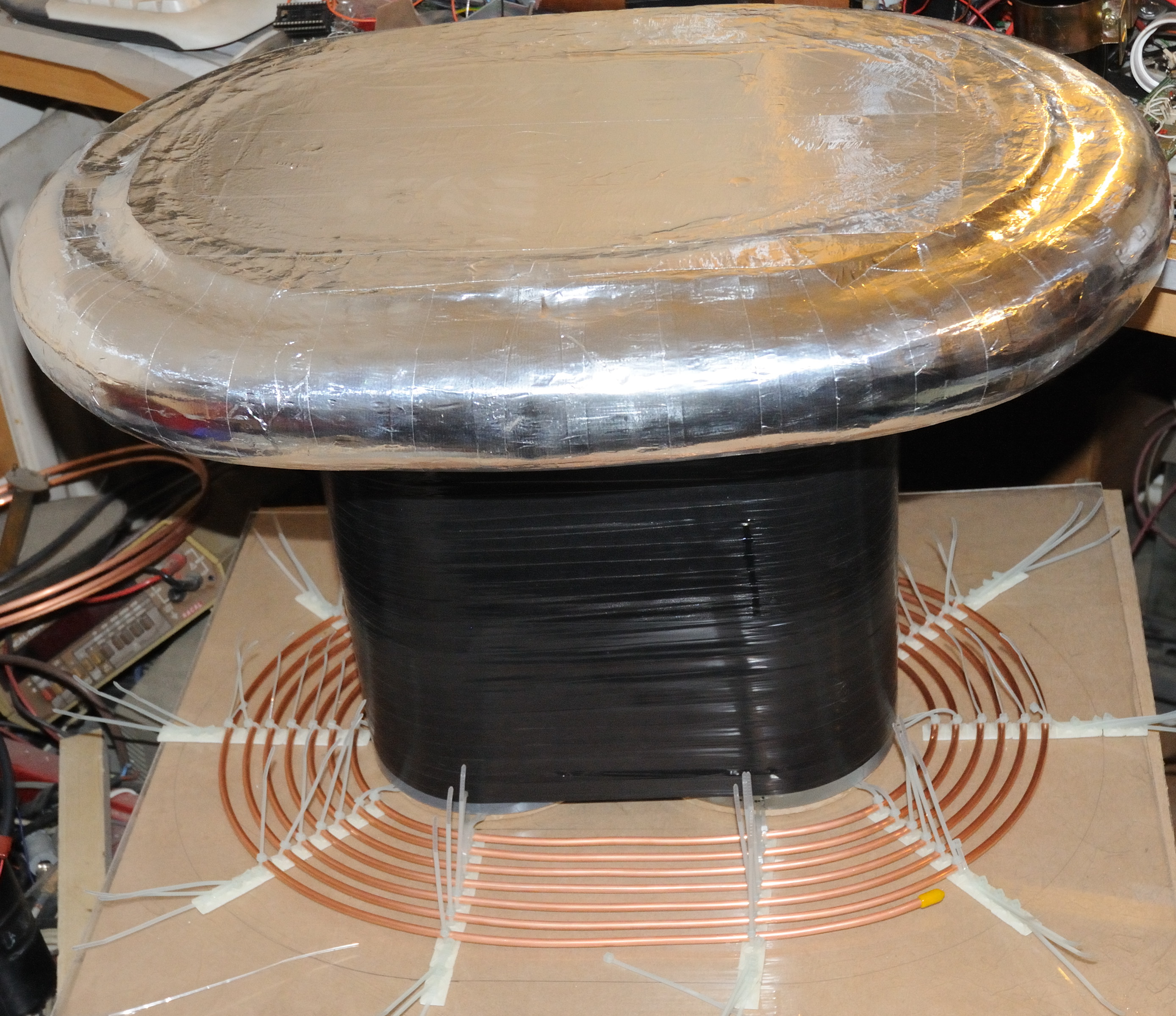
So I started with a topload that was big enough and strong enough to stand on. I started with a pair of 110mm PVC tubes and joined them together. The thought was to make an oval tesla coil (big mistake).
After winding the secondary, by hand (1000T of 0.33mm wire ) on to the former I started to realise that there was a problem, the wire stretched slightly and started to sag between the two tubes. To give the wire some support I wound PVC tape around the coils as I completed them. This was partially successful, but as I had nothing to loose so I continued.
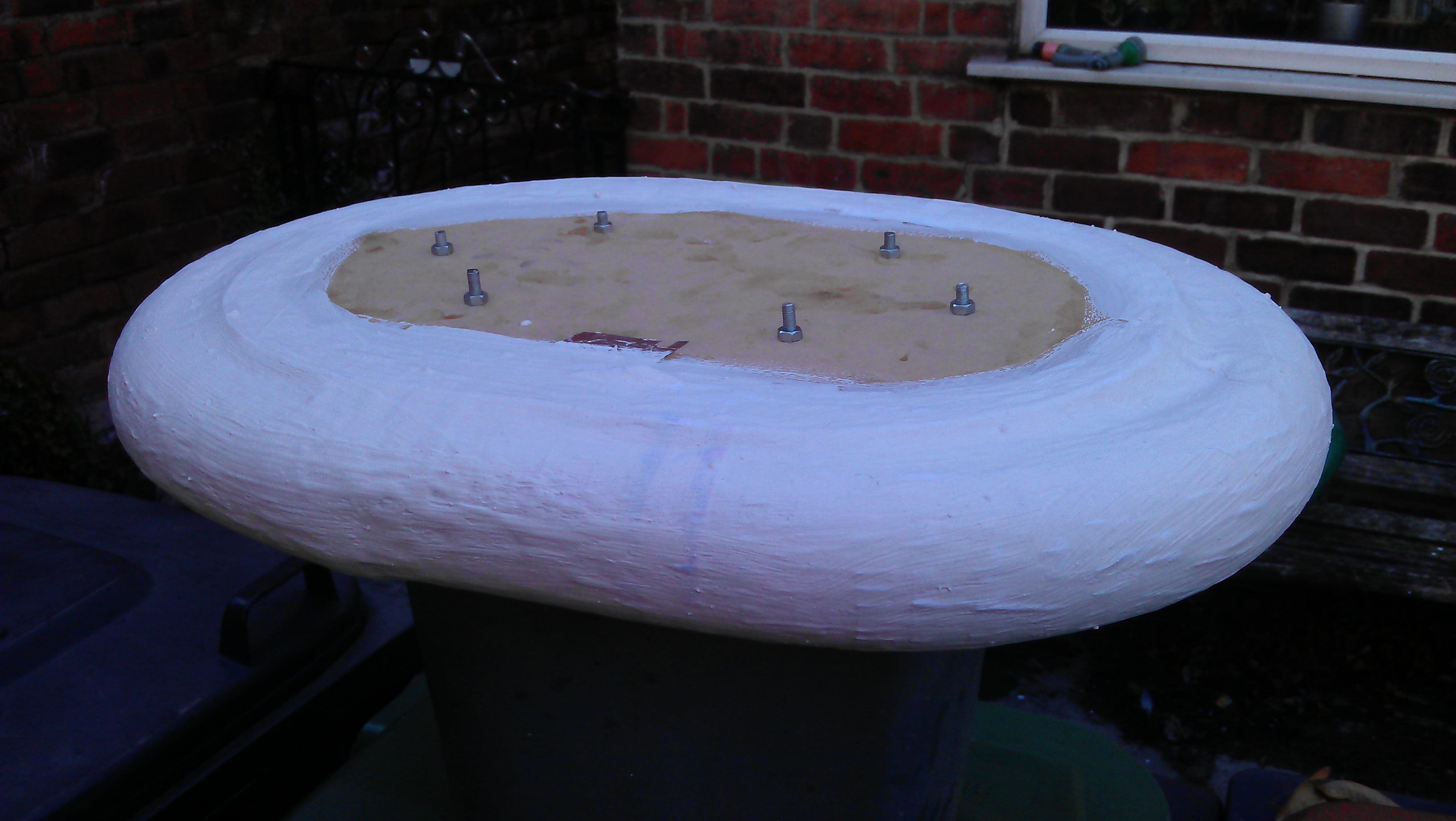
The Topload needed to be strong enough to
stand on too and smooth and an oval.
So I started with an MDF former of 3 oval sheets spaced to a total height of 2.5″, and an external wrap of pipe lagging to give the external shape.
Over this I added paper mache and then a covering of plaster and PVA glue to give it strength. This last layer could be sanded to smooth out the edges.
 The Primary, I quickly roughed out from 50′ of 5mm break pipe held in an oval spiral with cable ties and adhesive.
The output from the V8 tesla engine is fed into a primary cap and an crude sparkgap.
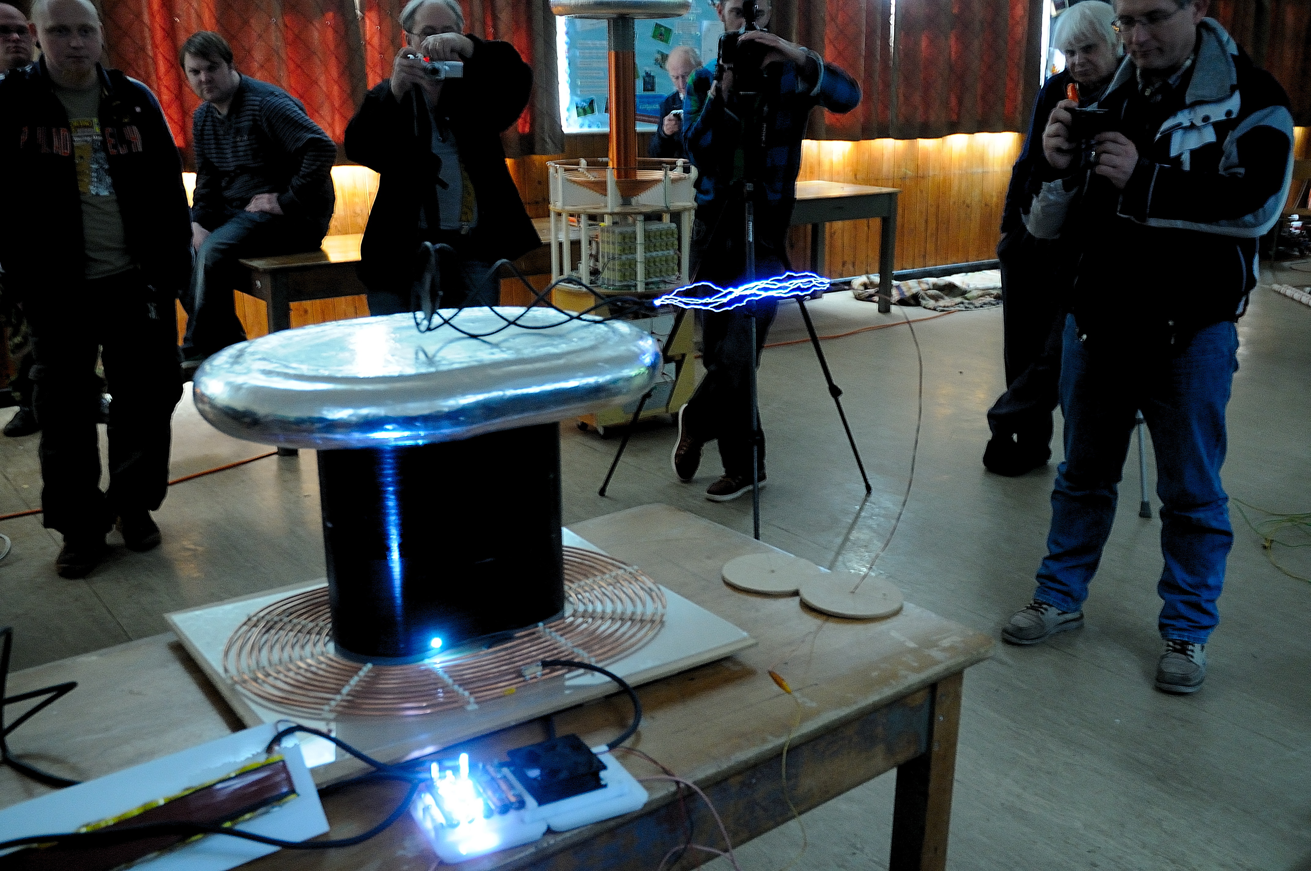
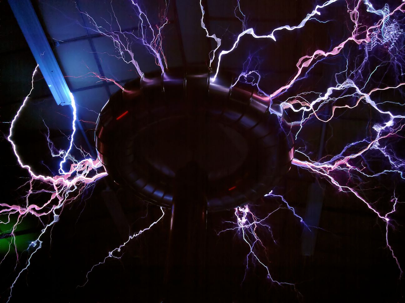
Here is the coil working at the Nottingham Gaussfest.
Note that the problems with the secondary coil are starting to show with a breakout at the bottom.
But it was worth having a go at standing out the coil. After a while I found that the tuning point changed only a single turn when I was standing on the coil.
Below is a video of the first run with me on top.
So I realised that the secondary needed to be re-built The pictures below show the damage.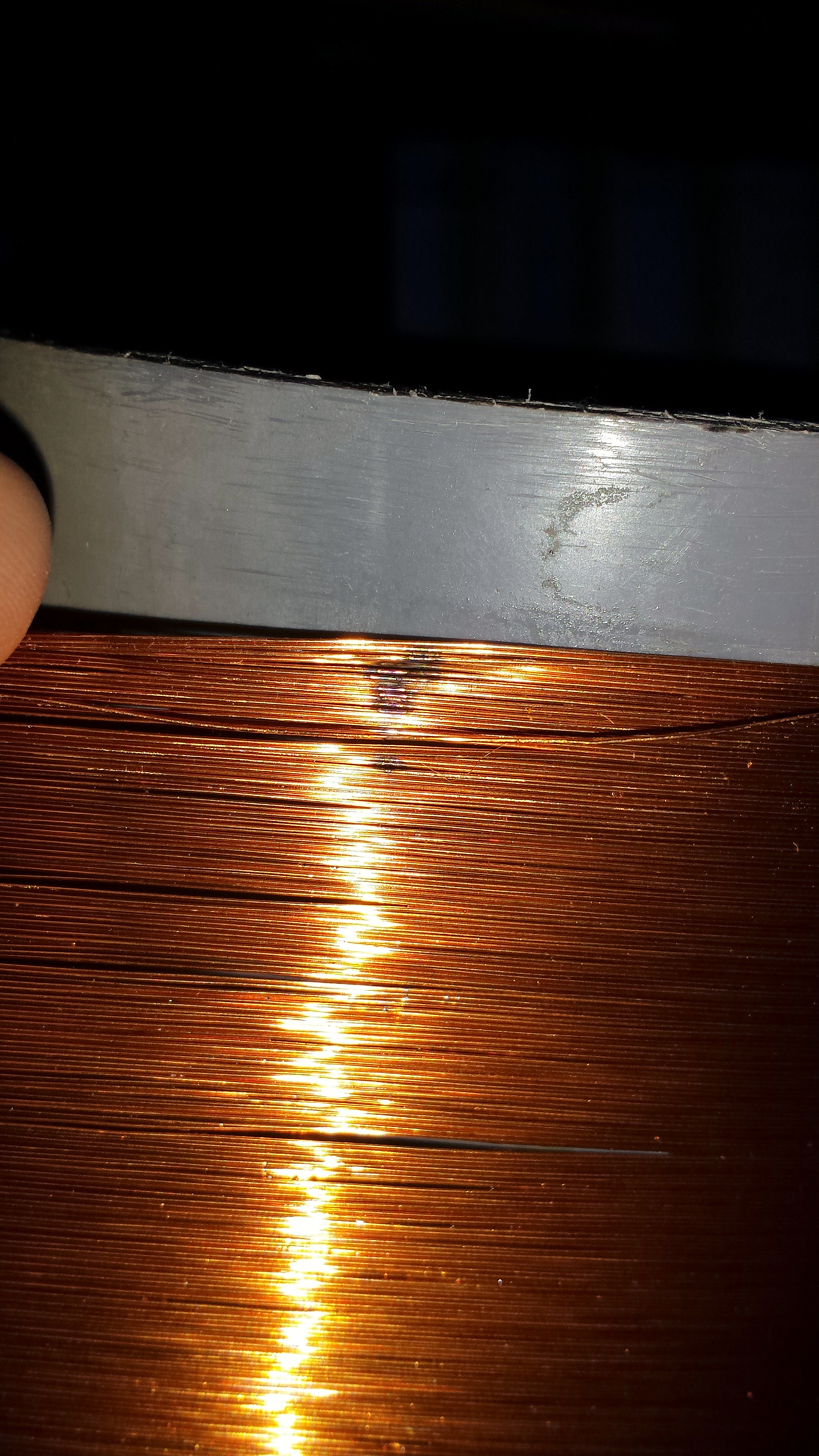
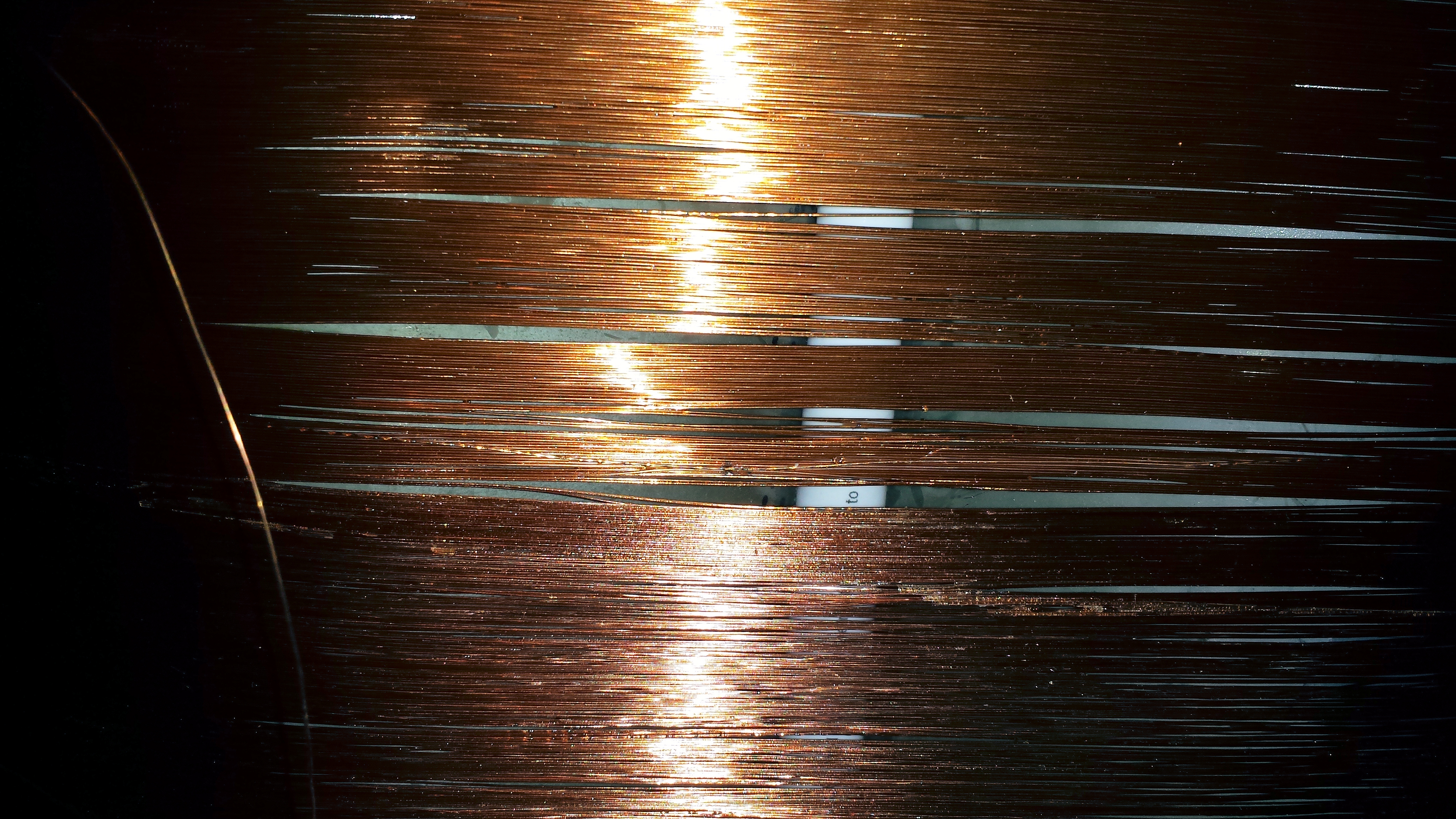
So the rebuild begins
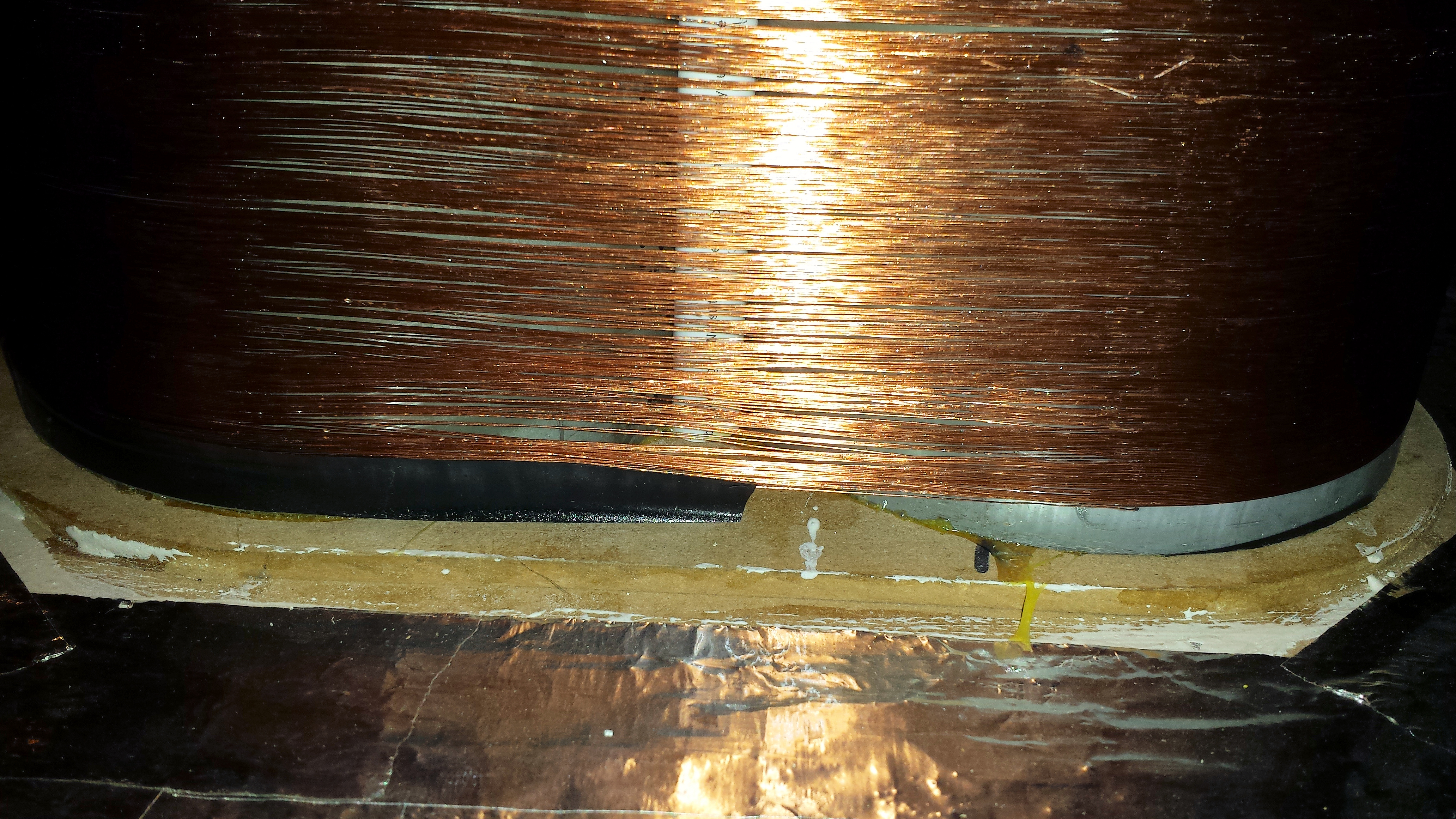
This time I’ve packed out the space with some cardboard in the void between the PVC pipes and sheets under the coil bridging the two pipes. The cardboard is held in place with many layers of adhesive craft paper that was varnished before the wire was wound on.
The finished article looks a load better then the old one, but there is still some minor ‘droopage’ between turns. So the coil was heavily varnished after winding.
Hopefully it will not suffer the same breakouts as the old.
Also I decided to clean and re-mount the sparkgap the old copper pipe gaps were a little? corroded.
The Sparkgap is mounted on to a channelled acrlyic chamber that allows a high volume fan to blow air over the gaps for cooling and more importantly spark quenching.
Better results from the new coil
First light of a Tesla Coil tuner.
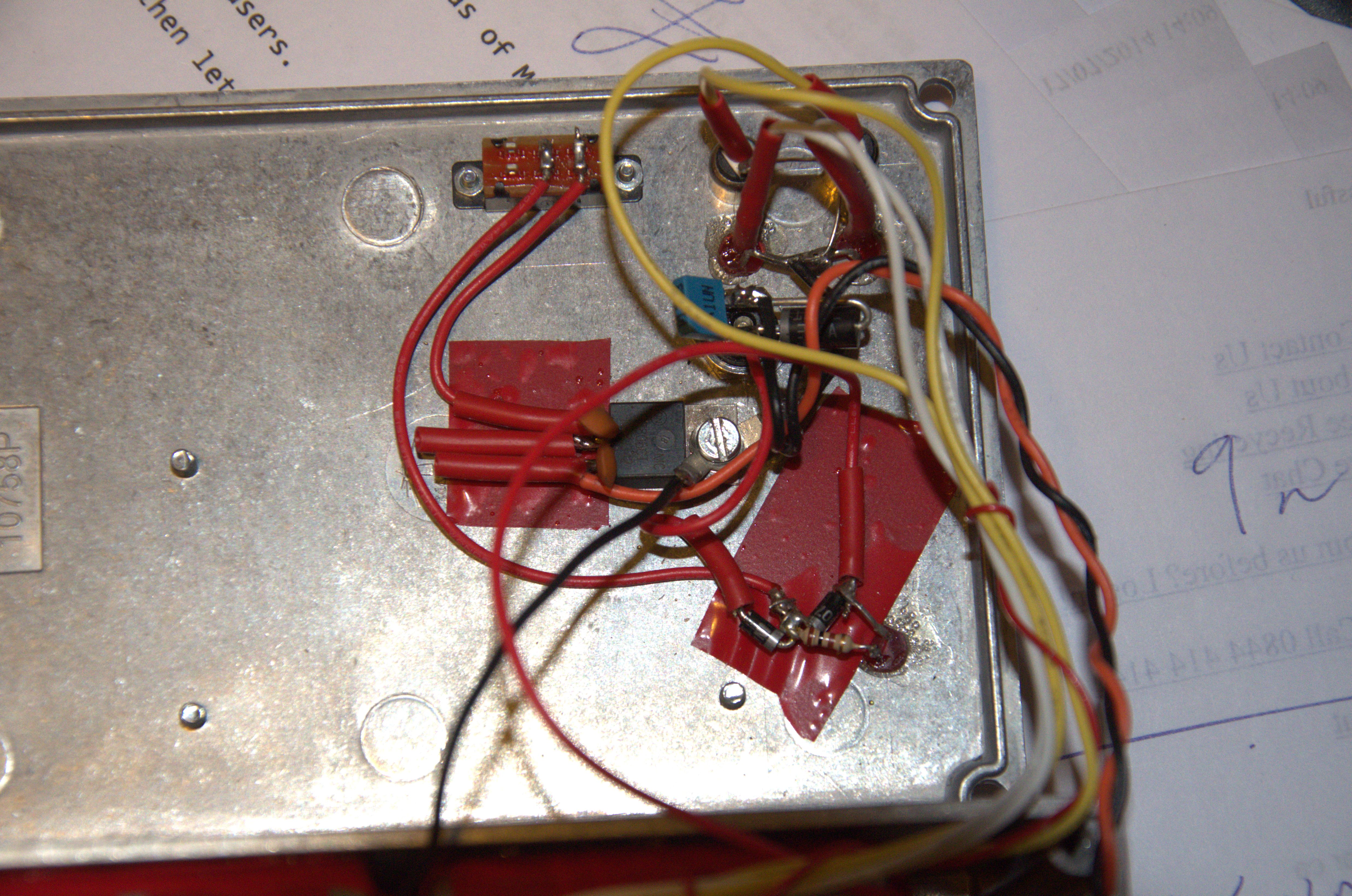
 So I needed to get a better Tesla coil Tuner. I have been using this NE555 pinger for 10+ years.
Always said I’d put it in a box.. Never happened…
With some of the tuning problems I’ve had recently I needed a better solution.
So..
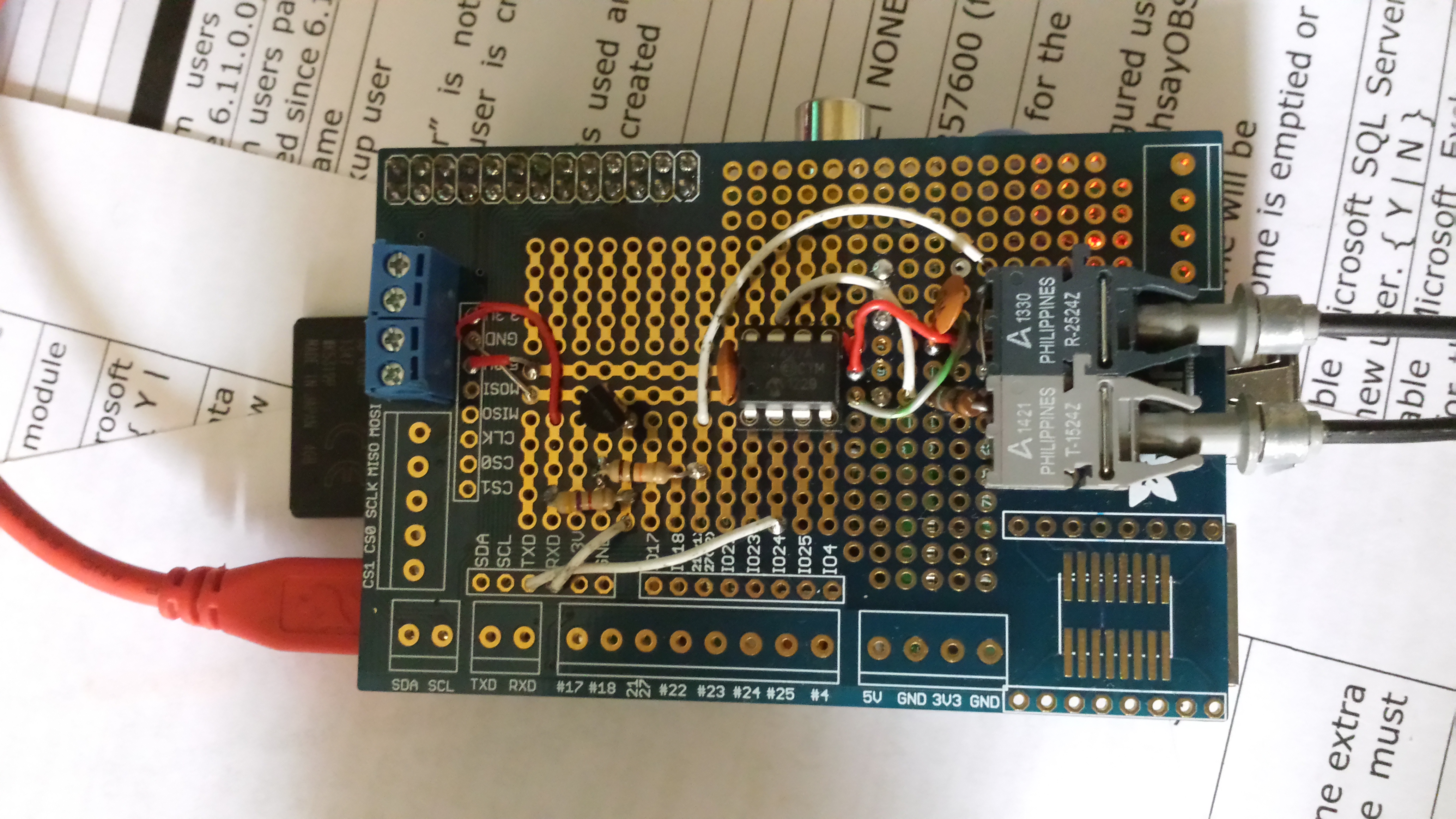
PIC powered USB controlled Tesla Coil Tuner using AD9850 DDS Frequency Synthesis.
Built on a PIC low pin count, USB development board (hence redundant RS232 connector)
Direct connection to the Primary Coil with current measuring.
Three ways of measuring.
Primary and cap on its own(Secondary removed)
Secondary on its own (driven by primary with no Primary cap)
Primary Cap and Secondary (across spark gap) – Should see both current dips.
First plot of a small Secondary coil, using VB to drive the USB.
Plots at ~15 seconds for 1000 points (e.g will scan from 500Khz to 1.5Mhz in 1khz steps in ~15 seconds.)
Range 50Khz to 4Mhz (with some droop at each end)
I’m having some issues getting a plot with just a primary coil, not sure why at the moment. Also my driver (tc428) is damaged, its not driving correctly to ground. Which may be causing me some issues. But not bad for a first go.
More developments
Added an Ariel input (B)
Improved the display, and removed a whole load of noise on the traces.
Also, added the ability to take snapshots of the traces (pale colours) so you can see any change from scan to scan
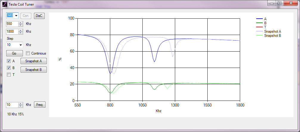
This shows a current scan in Dark blue, with a snapshot in light blue and the Ariel input in dark green with a light green snapshot. The current scan was done with my hand near the topload hence the lower resonant frequencies.
This clearly shows the primary (C & L) as a large dip on the left and the secondary / topload as the smaller dip on the right. I’m feeding the primary coil and primary cap in parallel as this gives the best indication of the current change in the primary. For some reason driving the coil with Cpri in series shows a lumped resonance (or doesn’t show the primary resonance up at all)
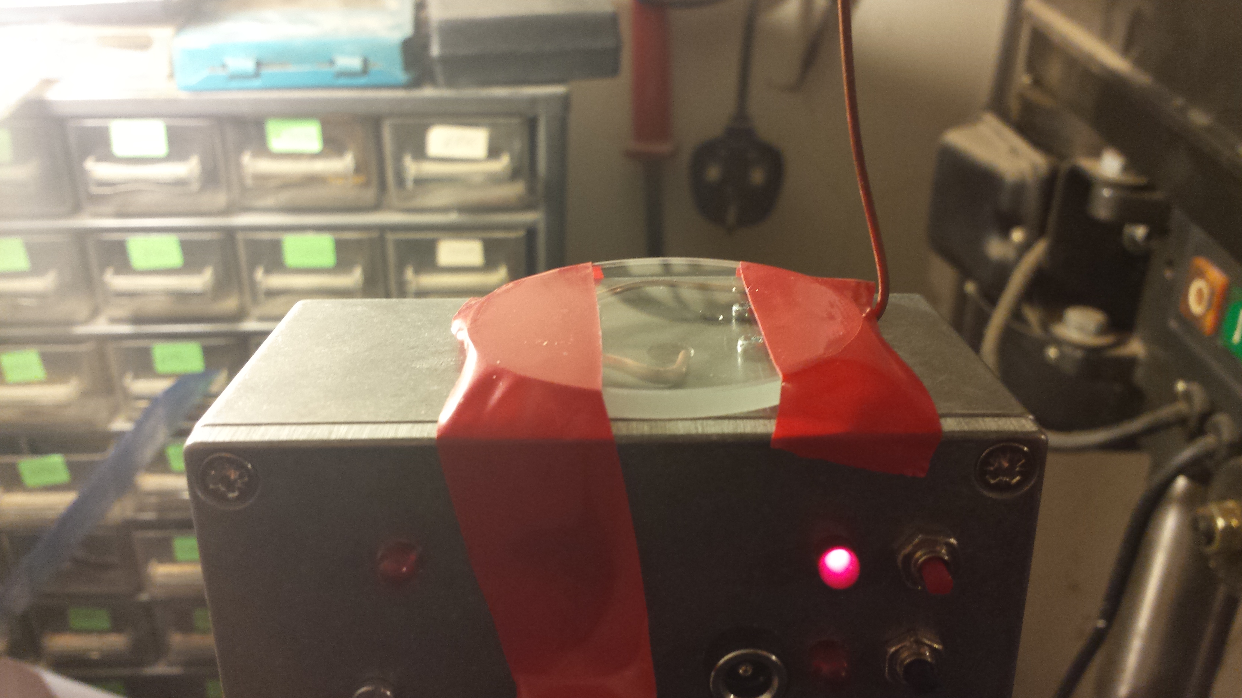
A raspberry Pi that will stand the most intense electromagnetic and electro static environments and cope with EMP (Electro Magnetic Pulse). The sort of environment around tesla coils.
I started with a Pi and a Adafruit Pi-Plate. My first job was to create a optic-fibre link (115Kb/s) for comms to my tesla coils and it also doubles up as a remote and insulated tty console for the PI. The chips I used for the fibre are the Avago 1524/2524 1Mb/s fibre transmitter/receiver.
The transmitter is driven from a Microchip TC4428 which takes the 3.3v TX to 5V and gives the current drive for the TX LED .The RX is level shifted and inverted using a BC337 (update – a speed up cap was added to the base as at 115kb Rx errors were seen)
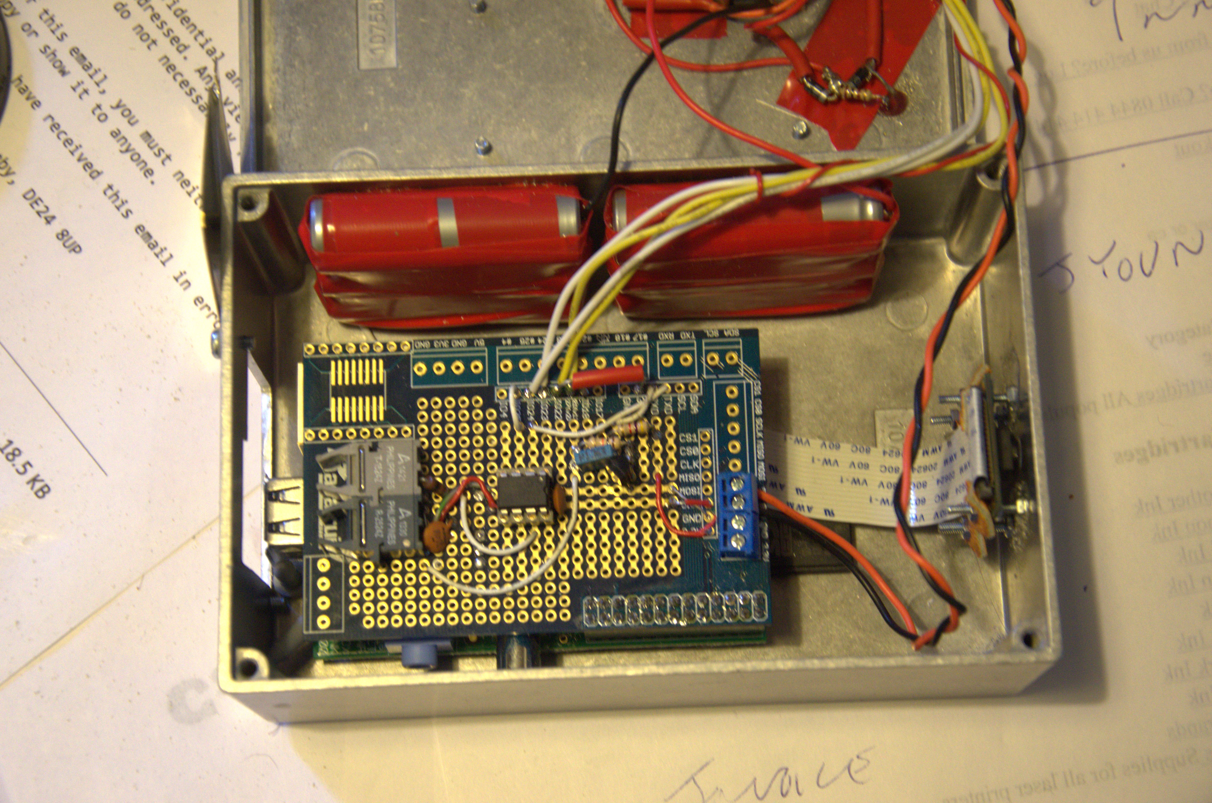
I realised that the Pi would have to run on its own power supply, so 6 rechargeable AA cells giving 7.2V were added, along with a 7805 regulator to give 5V for the Pi and a couple of diodes to allow the batteries to smoothly take over when the external power was removed.
As the power connector is open to the EM noise on the out side of the case, there is a diode , a cap and a 30V TVS across the power input.
It also became apparent that there was no way of cleanly switching off the Pi without connecting a network or terminal. So I added a button and a script to shutdown the Pi (although not cut the power).
A Pi Cam was attached and bolted to the case, A small hole lets it see the outside world without letting in too much radiation. I also added in a sedcond button which allows the camera to be turned on and off. The script makes the camera take photos every 10 seconds. (I hope to add video too)

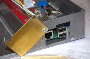
I added a removable panel that cover’s the USB, Ethernet and Fibre ports. This is not ideal as I can’t close it fully when I’m running on fibre.
I also added a shutter that goes across the external power/charging connector to further protect the circuits.
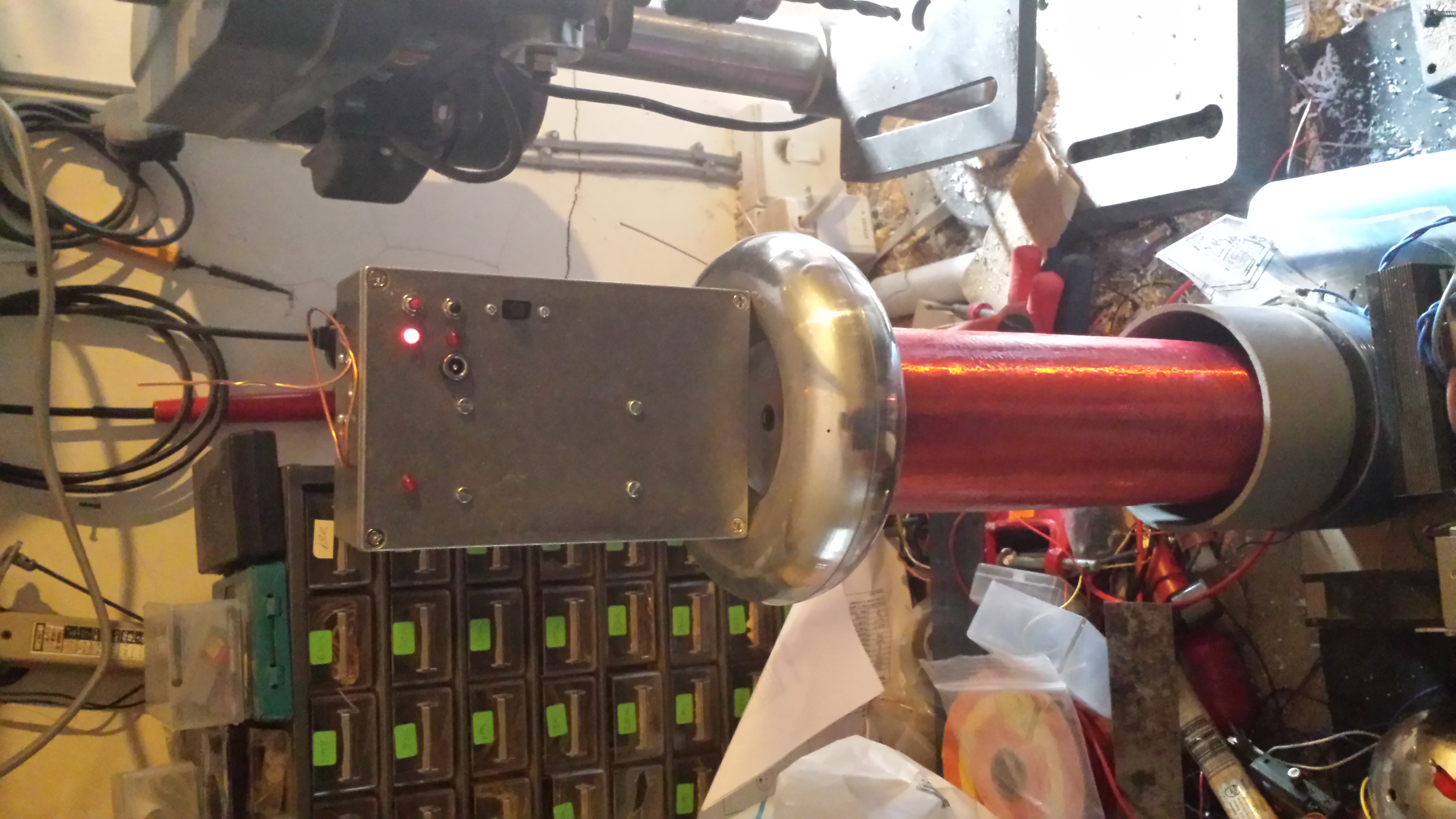
A quick test proved that the Pi can run when sat on top of a small tesla coil.
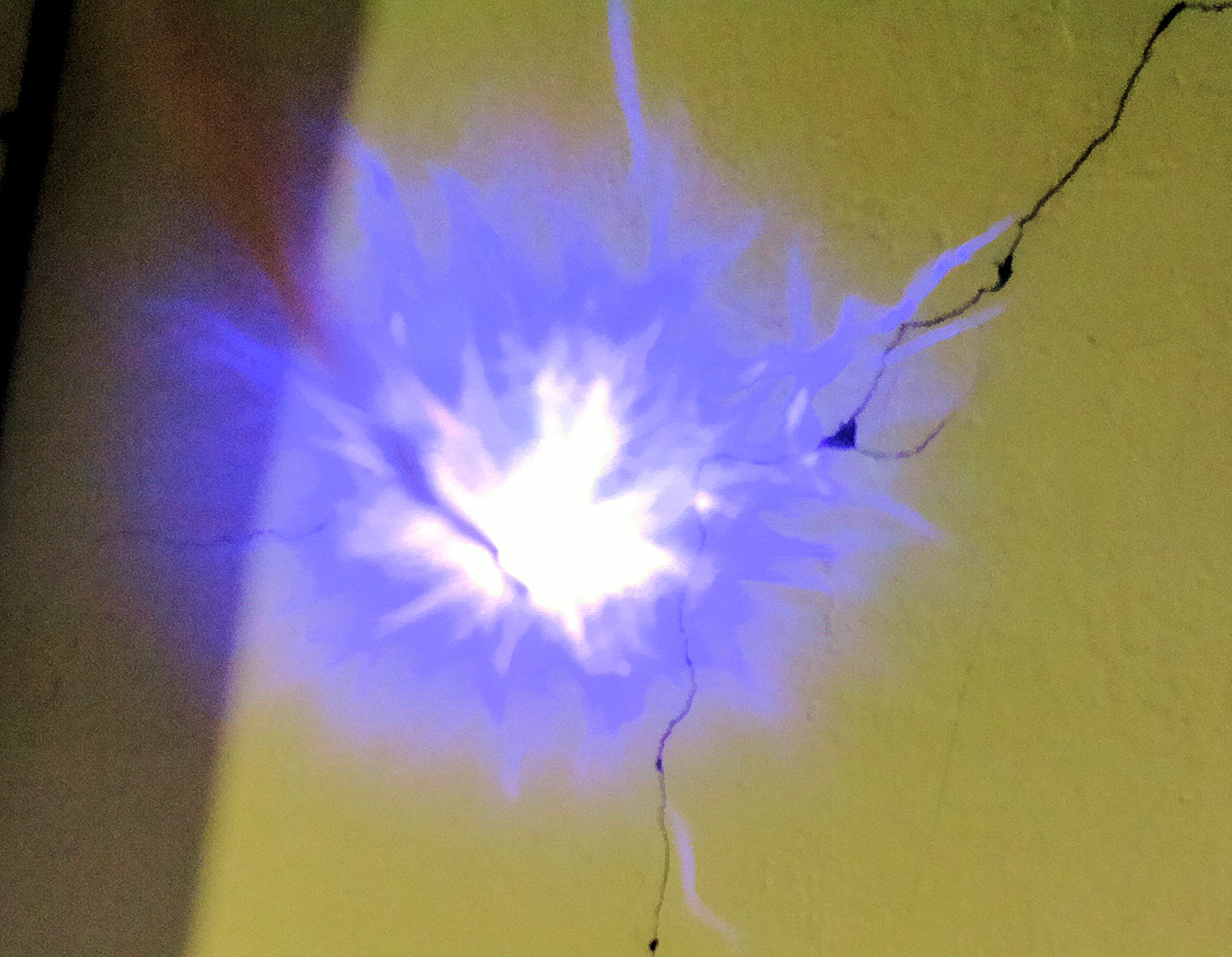
The camera also worked, but the breakout was too close for the camera to give good photos.
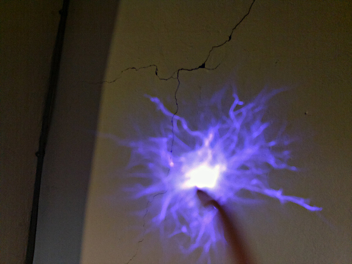
A monocle (50mm lens with 50mm focal length) was added
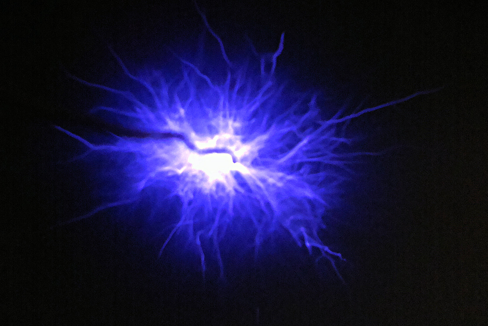
Giving a couple of goodish photos of the discharge from under the breakout point. (breakout is the wiggly black line to the LHS)
http://www.extremeelectronics.co.uk/empi-cambridge-teslathon-2014/
http://www.extremeelectronics.co.uk/tesla-coil-slow-motion-video-using-a-raspberry-pi/
Images from the EMPi cam at the Cambridge Teslathon
Video made from stills from the EMPi Camera (taked at 1fps, displayed at 5fps)
Composite of EMPi cam images
Quotations from the great man himself
“Invention is the most important product of man’s creative brain. The ultimate purpose is the complete mastery of mind over the material world, the harnessing of human nature to human needs.”
“What one man calls God, another calls the laws of physics.”
“The scientists of today think deeply instead of clearly. One must be sane to think clearly, but one can think deeply and be quite insane.”
“If your hate could be turned into electricity, it would light up the whole world.”
“I do not think there is any thrill that can go through the human heart like that felt by the inventor as he sees some creation of the brain unfolding to success . . . Such emotions make a man forget food, sleep, friends, love, everything.”
“All that was great in the past was ridiculed, condemned, combated, suppressed — only to emerge all the more powerfully, all the more triumphantly from the struggle.”
“But the female mind has demonstrated a capacity for all the mental acquirements and achievements of men, and as generations ensue that capacity will be expanded; the average woman will be as well educated as the average man, and then better educated, for the dormant faculties of her brain will be stimulated to an activity that will be all the more intense and powerful because of centuries of repose. Woman will ignore precedent and startle civilization with their progress.”
“It’s not the love you make. It’s the love you give.”
“Our virtues and our failings are inseparable, like force and matter. When they separate, man is no more.”
“I don’t care that they stole my idea . . I care that they don’t have any of their own”
“That is the trouble with many inventors; they lack patience. They lack the willingness to work a thing out slowly and clearly and sharply in their mind, so that they can actually ‘feel it work.’ They want to try their first idea right off; and the result is they use up lots of money and lots of good material, only to find eventually that they are working in the wrong direction. We all make mistakes, and it is better to make them before we begin.”
“The human being is a self-propelled automaton entirely under the control of external influences. Willful and predetermined though they appear, his actions are governed not from within, but from without. He is like a float tossed about by the waves of a turbulent sea.”
I have been asked this question so many time I thought I aught to write down the answer.
Musical tesla coils are fairly common now and there are many videos of them working, but what causes the noise.
So lets start with the basics. Most electronic tesla coils don’t run continuously (Ill come back to CW coils later). To maintain a large spark output current in the primary circuit is key, to get the best out of the components the coils are driven for short periods of time, at high currents, quite often exceeding the continuous rating of the drivers. During this short ‘on’ period, power is stored as in the primary and secondary coil. As soon as the power is turned off the stored energy is transformed into a high voltage high frequency pulse. It is this pulse that you see as the discharge from the top of the coil.
Creating hot plasma in the atmosphere has an effect, the air heats up to thousands of degrees C in a microsecond or so. This expanding air causes a sound wave that you hear as a click. (or a bang with real lightning, its just a matter of scale.)
So, if you repeat this process at say 263 times a second, you will hear an audio tone at middle C
Music can be played by controlling the length and frequency of the pulses you send to the coil. With these coils getting the frequency and length information is relatively simple from a MIDI audio source via a suitably programmed microprocessor.
Due to the pulsed nature of the coil real audio (e.g speech,singing etc) cannot be rendered.
OK, I mentioned CW (Constant or Carrier wave) Tesla coils
With CW coils the power isn’t interrupted they are driven constantly. Their output is essentially silent (You do get a hiss at lower frequencies due to variations in the spark output). To get music from these coils you vary the power going in to them in a very similar way to an AM radio transmitter. There is two ways of achieving this.
1) You control the voltage to the driver therefor controlling the power
2) You vary the frequency of the drive (FM modulation), The tuned circuit formed by the secondary gives maximum output only at the central frequency, so the effective output power is varied as the frequency is varied.
As the power is continuous, you can’t gain any power advantage by short pulses and neither do you get the voltage gain by the release of the stored power in the secondary so the sparks are smaller than a pulsed coil.
But, you can render speech, singing and any instrument can be played due to the almost radio style modulation. Plasma speakers are made using this technique.