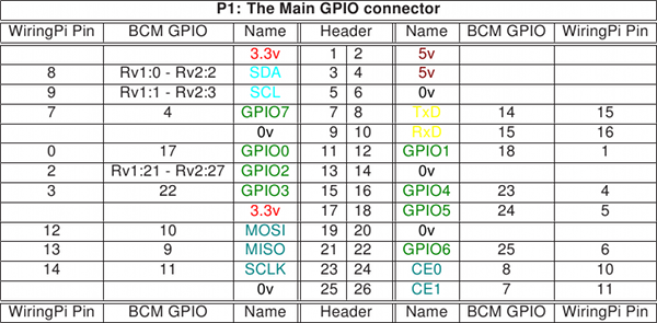
Im bound to lose this card, so a link to it so I know here it is
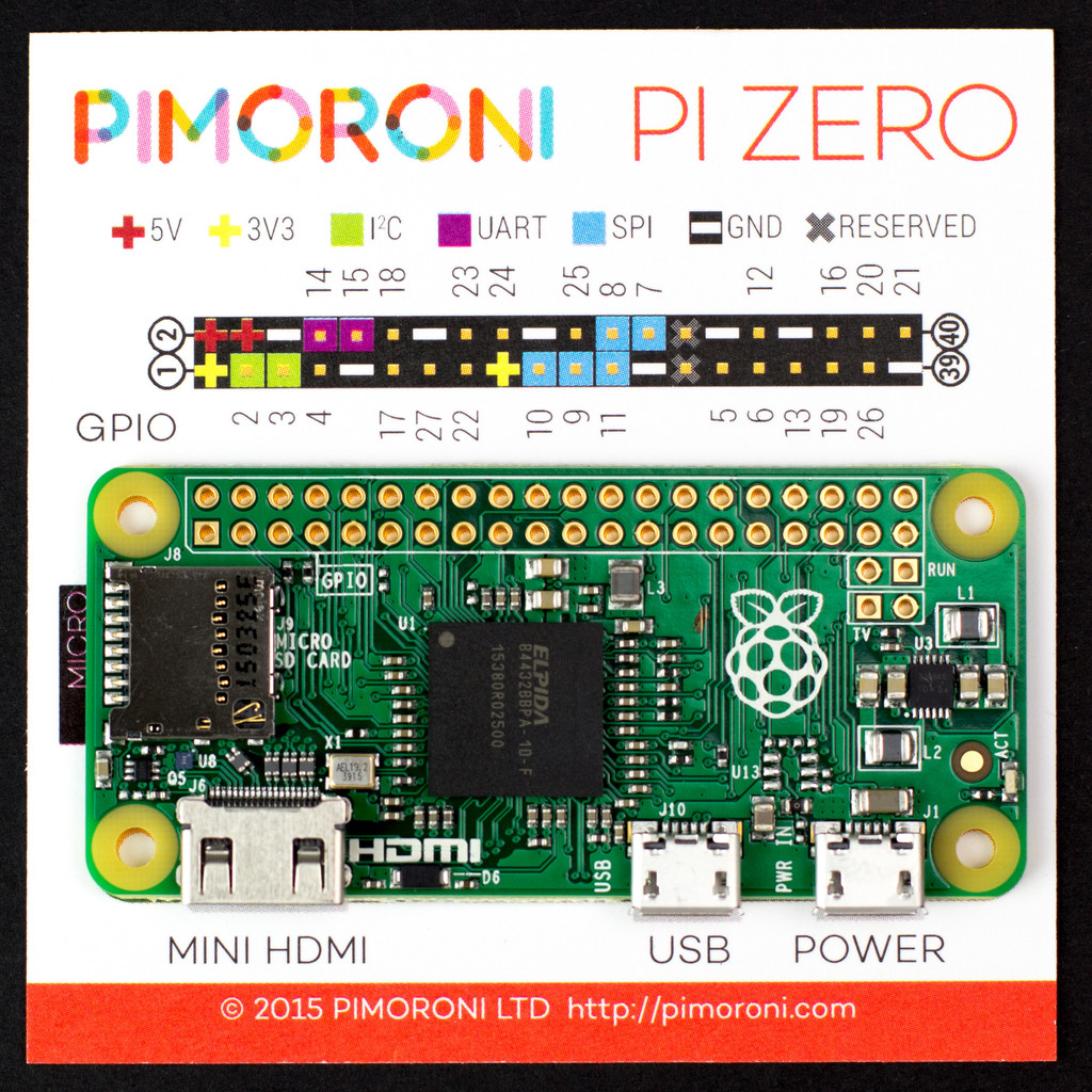
https://shop.pimoroni.com/products/raspberry-pi-zero

Im bound to lose this card, so a link to it so I know here it is
https://shop.pimoroni.com/products/raspberry-pi-zero
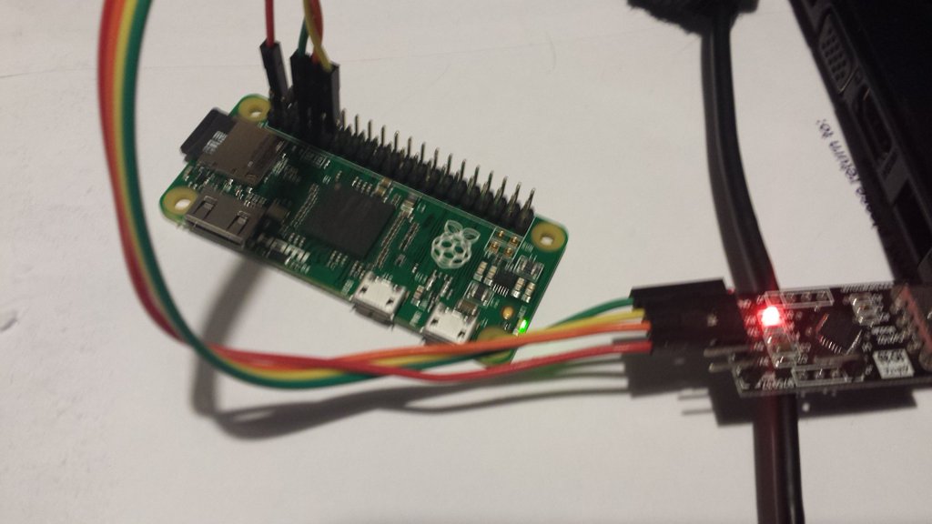
The PIZero Simple setup without network or monitor. (Requires some prior knowledge of RS232 adapters and serial port setup)
First start by getting a PI SD image I used Raspian Jesse Light https://www.raspberrypi.org/downloads/raspbian/
Install into a sd card and make sure it runs (green light at least)
With a 3.3v RS232 adapter connect earth and RX/TX to your PI. Be careful some adapters are only 5V and will damage your PI’s UART pins.
Setup your PC (I use Tera Term) serial adapter for 115200, 7 bits, even parity, 1 stop bit.
Boot your PI
If you get a screen of gobbledegook then good, otherwise swap your TX and RX around. When the gobbledegook has finished, press return a couple of times, and you should get a login prompt.
For some reason the console and boot up output at different baud rates (Caused by auto baud rate detect, settings above amended so this shouldn’t happen now)
Configure your PI the usual way. You will need some network to get your updates, but apart from that you have a working PI.
If you are brave (or idle) you can connect the +5v line from your serial adapter to power your PI too so you don’t need another usb power lead. Just be very careful that you attach it to the correct pins, otherwise your PI will be damaged.
Useful links.
(although I found the baud rate setting wrong everywhere I looked. Either auto baud rate detect at work, or it changes from distro to distro)
Element 14 no display using the raspberry pi serial console
Update:
The baud rate is auto detected, the native speed is 115200 (amended above) The auto detection only happens at the login prompt. The auto detection won’t pick up changes in bits/stop bits/ or parity. You can change the console getty port/speed/parity settings look at RPi serial connection above.
WiFi
If you have a wifi adapter and micro USB to USB lead, you can connect to WIFI. After connecting via RS232 edit the file /etc/wpa_supplicant/wpa_supplicant.conf using sudo nano
add in the lines
network={
    ssid="Your_WIFI_SSID"
    psk="Your_wifi_password"
}

and reboot the pi sudo shutdown -r

re log in to the pi and type ifconfig to fins the wifi IP address.
Then you can ssh to your PI and even better update the software.
Note : for Pi 3. You may need some changes to get the headless conf working, especially at non default baudrates, take a look at http://www.briandorey.com/post/Raspberry-Pi-3-UART-Boot-Overlay-Part-Two
So I bought a Minimus32 Development board from [shortlink url=”http://www.modtraders.co.uk/minimus-32-avr-usb-development-board.html” title=”Mod Traders”]
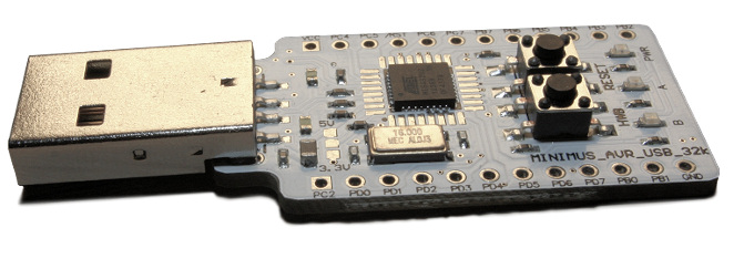
Couple of reasons for the purchase, Its was cheap, and it had a small processor and USB support out of the box.
OK, 1 and 2 are true, 3 is a little more complex.
After trawling the internet All I found was out of date information, information on the original Minimus board, or information using an old version of Atmels IDE. Having struggled in the past with old IDE’s I decided to use the newest one and brave it out.
So, For Windows…
You can download Atmel’s latest IDE free from here [shortlink url=”http://www.atmel.com/microsite/atmel_studio6/” title=”http://www.atmel.com/microsite/atmel_studio6/”] It is a Visual Studio based IDE and looks pretty good. Unfortunately there is no support for the bootloader contained in the minimus32 board.
So to get a hex image onto the Minimus 32 you need Flip downloadable for free here [shortlink url=”http://tinyurl.com/7jqeg3l” title=”http://www.atmel.com/tools/FLIP.aspx”]
Braving the new environment I cut and pasted a demo code sample (blink )
[code]#include <avr/io.h>
#define F_CPU 16.000E6
#include <util/delay.h>
#include <avr/wdt.h>
void init_ports(void)
{
PORTB = 0b00000000;
DDRB = 0b00000000;
PORTC = 0b00000000;
DDRC = 0b00000000;
PORTD = 0b00000000;
DDRD = 0b01100000; // Set LEDs as output
}
int main(void)
{
MCUSR &= ~(1 << WDRF);
wdt_disable();
init_ports();
while(1)
{
if (PIND & 0b10000000) {
PORTD = PORTD & ~0b01000000;
PORTD = PORTD | 0b00100000;
_delay_ms(200);
PORTD = PORTD & ~0b00100000;
PORTD = PORTD | 0b01000000;
_delay_ms(200);
} else {
PORTD = PORTD | 0b01100000;
}
}
}
I set the uP to ATMEGA32U2 hit build and It compiled first time.
Went into Flip, loaded the .hex file and sent it to the Minmus32. After a little playing with the buttons it ran.
(Tip: to put the Minimus into “Load” mode you need to press RESET, press HWB, release RESET and release HWB, just roll your finger over the buttons)
So a USB example.
I found that you can get the latest version of the LUFA libraries from here [shortlink url=”http://tinyurl.com/mx8flmo” title=”http://gallery.atmel.com/Products/Details/47ba24a4-d17b-4fed-b244-f5998b3d789d”] and the are already formatted for Studio 6
Loaded the Libraries and tried the demo project for USB to RS232
It compiled, but wouldn’t run.
Cutting a long story short there were a number of things wrong. The Processor speed was incorrect, the target board wasn’t set correctly and the LUFA libraries didn’t contain the code specific to the Minimus32 Board.
So. to fix these.
In Atmel Studio 6, Goto Project->Toolchain -> AVR/GNU C Compiler -> Symbols
Ensure they look like this
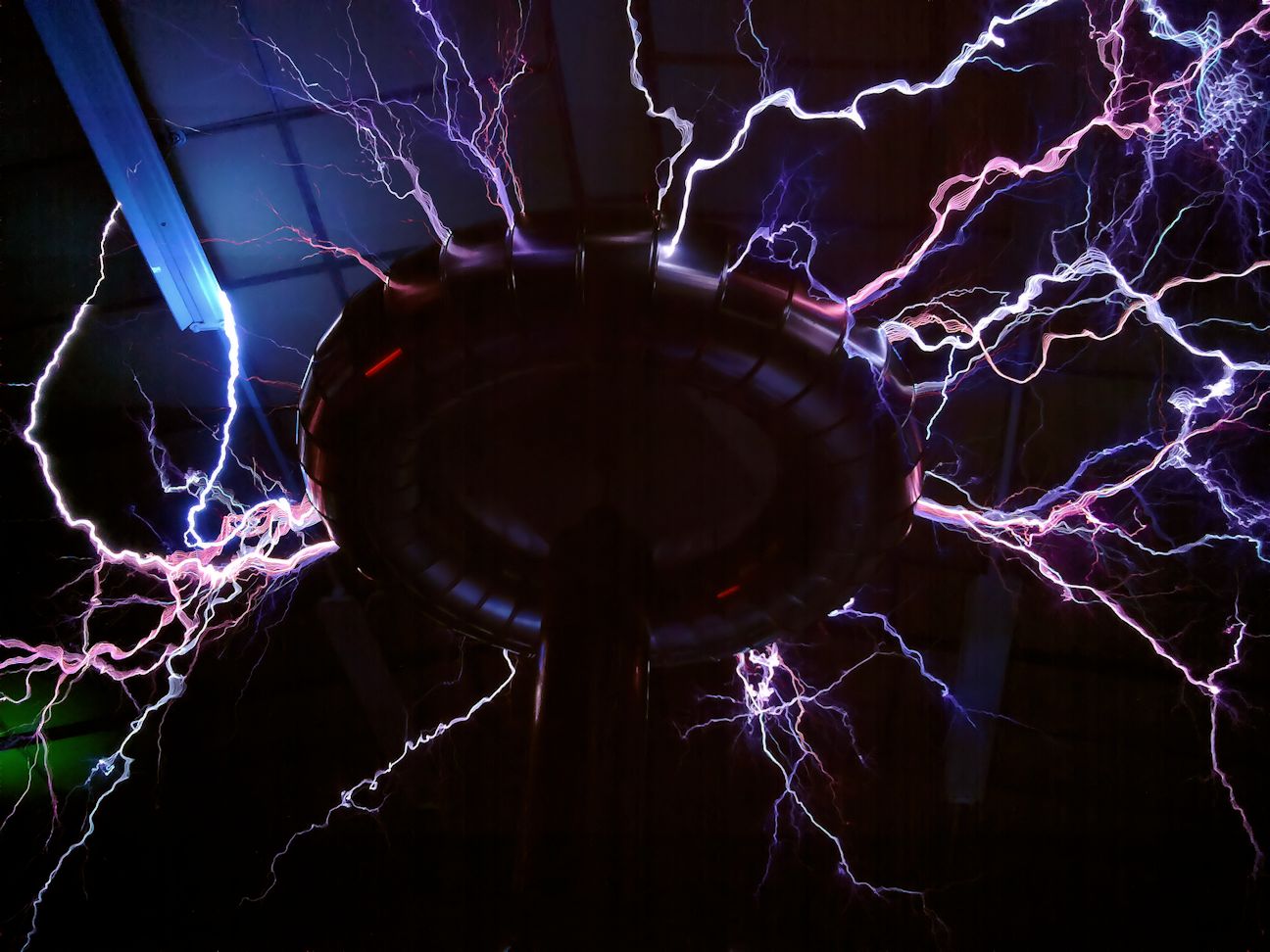
[code] F_CPU=16000000ULFirst light of a Tesla Coil tuner.
 So I needed to get a better Tesla coil Tuner. I have been using this NE555 pinger for 10+ years.
Always said I’d put it in a box.. Never happened…
With some of the tuning problems I’ve had recently I needed a better solution.
So..
PIC powered USB controlled Tesla Coil Tuner using AD9850 DDS Frequency Synthesis.
Built on a PIC low pin count, USB development board (hence redundant RS232 connector)
Direct connection to the Primary Coil with current measuring.
Three ways of measuring.
Primary and cap on its own(Secondary removed)
Secondary on its own (driven by primary with no Primary cap)
Primary Cap and Secondary (across spark gap) – Should see both current dips.
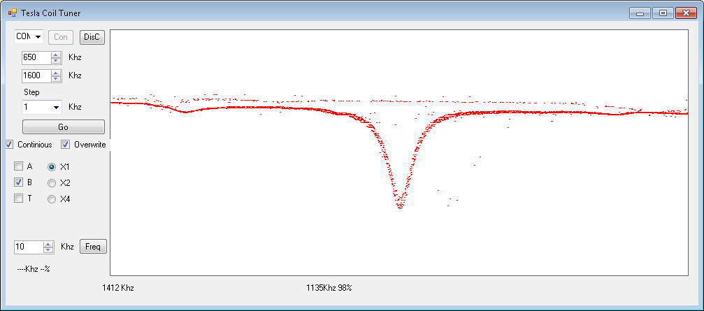
First plot of a small Secondary coil, using VB to drive the USB.
Plots at ~15 seconds for 1000 points (e.g will scan from 500Khz to 1.5Mhz in 1khz steps in ~15 seconds.)
Range 50Khz to 4Mhz (with some droop at each end)
I’m having some issues getting a plot with just a primary coil, not sure why at the moment. Also my driver (tc428) is damaged, its not driving correctly to ground. Which may be causing me some issues. But not bad for a first go.
More developments
Added an Ariel input (B)
Improved the display, and removed a whole load of noise on the traces.
Also, added the ability to take snapshots of the traces (pale colours) so you can see any change from scan to scan
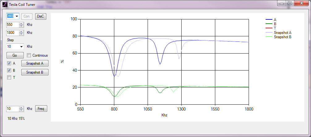
This shows a current scan in Dark blue, with a snapshot in light blue and the Ariel input in dark green with a light green snapshot. The current scan was done with my hand near the topload hence the lower resonant frequencies.
This clearly shows the primary (C & L) as a large dip on the left and the secondary / topload as the smaller dip on the right. I’m feeding the primary coil and primary cap in parallel as this gives the best indication of the current change in the primary. For some reason driving the coil with Cpri in series shows a lumped resonance (or doesn’t show the primary resonance up at all)
Images from the EMPi cam at the Cambridge Teslathon
Video made from stills from the EMPi Camera (taked at 1fps, displayed at 5fps)
Composite of EMPi cam images