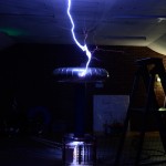
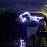
All posts by EEadmin

Mini Maker Fair Derby

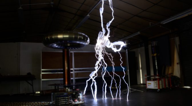
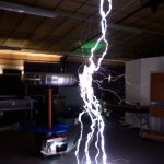
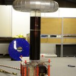
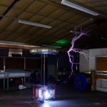
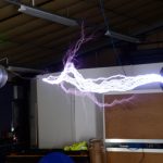
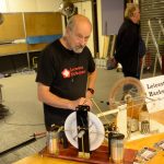
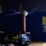
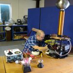
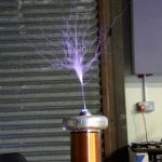
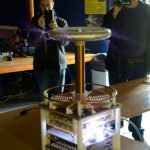
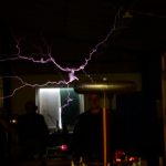
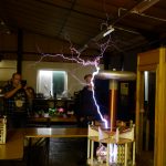
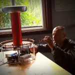
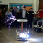
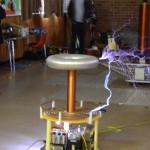
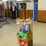
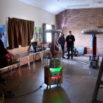
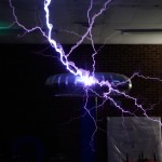
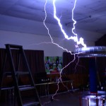
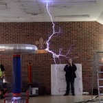
Come and Meet Extreme Electronics and the Twin PI tesla coils (and some other stuff 🙂 at Derby Mini Maker faire. We will be by the jet engine just off the main hall.

[gview file=”http://www.extremeelectronics.co.uk/wp-content/uploads/2016/10/Maker-Faire-2016-poster.pdf”]

Talk for Derby Geekeasy 11-8-16

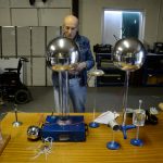
HV talk in the Furnace inn in derby for Derby Geekeasy @geekeasyderby

Thanks to the people at the Derby Geekeasy for a great night, plus a special thanks for the staff of the furnace inn for being very accommodating (and having excellent beer)

Videos (thanks to Glyn)

If you would like a HV or Tesla talk in the Nottingham, Derby or Leicester area, please contact me.
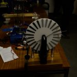
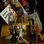
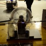
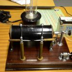
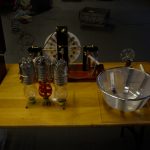
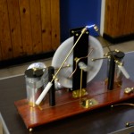
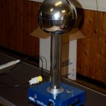
The Wimshurst Machine

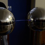
Wimshurst – Pinpong ball particle accelerator

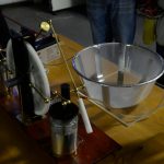
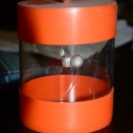
Wimshurst – Bottle motor

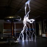
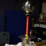
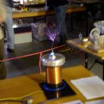
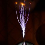
Part 2 – Tesla coils

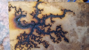
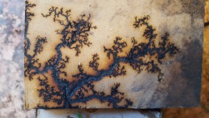
Lichtenburg figures for the BBC One Show

Ok so it started as one of those phone calls that asks if I can make safe sparks. Quite a regular ask for me and I always start with no. High voltage isn’t safe.

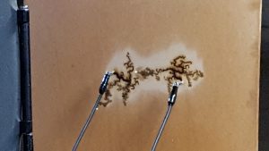
Anyway after a number of discussions. I was asked to make a “relatively” safe way of allowing a BBC presenter to create lichtenburg figures.

The method I came up with was to use a 15KV OBIT (Oil Burner Ignition Transformer). I prefer this type of transformer to a MOT (Microwave Oven Transformer) for purely safety reasons. One touch from an MOT and you are either Burnt, Dead or Burnt and Dead, Not good odds. This is due to them giving up to 100mA at 2KV, plenty to get 1-2mA across the heart of the unwary. The other issue with MOT’s is they are low enough voltage not to cause corona, which means they are silent, a dangerous mix. OBITS on the other hand give out 10-15Kv at 5-10mA. Not safe, but you are much more likely to survive an accidental contact.  Also due to the OBITs high voltage, you can hear when they are on.

The Control.

20160704_152207

20160704_152117

The boxes were split in to two, the Transformer and high voltage at the “HOT” end and the lower voltage (mains) at the other.

The control box had a key lockout which needed to be in place for the HV to be turned on. This key was attached to me with a short lead so I could ensure the HV area was safe before I allowed any power to the box. The Go button was momentary, so that if any danger was spotted the power could be quickly removed.

The HV end was in a roped off area (out of shot)

The mains was supplied via an earth leakage trip for added safety.

20160426_123838

The HV end was supplied via 30KV insulated cable to two crock clips that attached to the screws on the board.

The board was dampened with water and washing up liquid, (required to properly soak more than just the surface of the board)

20160426_131831

This really is a don’t try it at home experiment, when the power is on, you can’t touch ANYTHING, damp wood, water and high voltage  not a good mix.

Luckily the presenter was Marty Jopson a HV fan so the explanation and safety briefing was fairly easy as he understood the risks. (He has his own collection of HV equipment including a one Tesla.)

20160426_125954sm

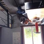
This was all done in the most glamorous of locations 🙂

20160426_123534

The result. No one died… and I think they got a good film of the Lichtenburg figures being produced.  I will find out 19:00 BBC1 4th July 2016.

Other Making Lichtenburg links

Lichtenburg figures with toner

Lichtenburg figures over water

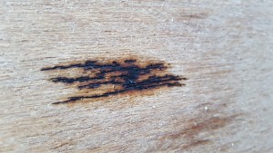
Lichtenburg figures in wood.


Save

Save

Save

Save

Save

Save

Save

Save

Code to write to I2C YwRobot display from PI command

Compile with  gcc -o i2c_lcd i2c_lcd.c -l wiringPi

Usage:
i2c_lcd -i  init display
i2c_lcd -c  clear display
i2c_lcd -1:2:3:4 “text”  print text to line 1:2:3:4

#include <stdlib.h>
#include <stdbool.h>
#include <stdio.h>   /* Standard input/output definitions */
#include <string.h>  /* String function definitions */
#include <unistd.h>  /* UNIX standard function definitions */
#include <fcntl.h>   /* File control definitions */
#include <errno.h>   /* Error number definitions */
#include <termios.h> /* POSIX terminal control definitions */
#include <time.h>

char * lockfile="i2c_lcd.lock";
int i2c_address=0x27;
int fd;
bool backlight=true;
int last_data;

void init_lcd(void);
void I2CWriteDirect(int);
void I2CWriteDirectBl(int);
void lcd_strobe(void);
void lcd_write(int);
void lcd_puts(char *, int );
void test_write(void);
void lcd_write_char(int);
void lcd_clear(void);
void lcd_cursoroff(void);
void checklock(void);
void clearlock(void);
void AllLines(char * );

void main(int argc, char *argv[]){
wiringPiSetup();
if (false==(fd=wiringPiI2CSetup(i2c_address))){
fprintf(stderr,"Can't open i2c on port %i\n",i2c_address);

exit(1);
}

if (argc==1){
printf("Usage:\n");
printf("i2c_lcd -i  init display\n");
printf("i2c_lcd -c  clear display\n");
printf("i2c_lcd -1:2:3:4 \"text\"  print text to line 1:2:3:4\n");
printf("\n");
}

int i;
for (i = 1; i < argc; i++)  /* Skip argv[0] (program name). */
{
if (strcmp(argv[i], "-i") == 0)  /* Process optional arguments. */
{
init_lcd();
lcd_cursoroff();
}
if (strcmp(argv[i], "-1") == 0)  /* Process optional arguments. */
{
checklock();
lcd_puts(argv[i+1],1);
}
if (strcmp(argv[i], "-2") == 0)  /* Process optional arguments. */
{
checklock();
lcd_puts(argv[i+1],2);
}
if (strcmp(argv[i], "-3") == 0)  /* Process optional arguments. */
{
checklock();
lcd_puts(argv[i+1],3);
}
if (strcmp(argv[i], "-4") == 0)  /* Process optional arguments. */
{
checklock();
lcd_puts(argv[i+1],4);
}
if (strcmp(argv[i], "-c") == 0)  /* Process optional arguments. */
{
checklock();
lcd_clear();
}
if (strcmp(argv[i], "-f") == 0)  /* Process optional arguments. */
{
checklock();
AllLines(argv[i+1]);
}

}

clearlock();

//   init_lcd();
//   lcd_clear();
//   test_write();
//    lcd_puts("test string",3);
//    lcd_puts("Last line",4);
}

void checklock(void){
if( access( lockfile, F_OK ) != -1 ) {
printf("Lock Exists\n");
while(access( lockfile, F_OK ) != -1 ){usleep(10000);}
}
FILE *fp = fopen(lockfile, "ab+");
}

void clearlock(void){
if( access( lockfile, F_OK ) != -1 ) {
unlink(lockfile);
}
}

void I2CWriteDirectD(int data){
data=data & 0xFF;
I2CWriteDirect(data);
last_data=data;
}

void I2CWriteDirect(int data){
data=data & 0xFF;
if (backlight){
wiringPiI2CWrite(fd,data | 0x08);
}else{
wiringPiI2CWrite(fd,data);
}
}

void lcd_strobe(void){
usleep(400);
I2CWriteDirect((last_data | 0x04));
usleep(400);
I2CWriteDirect((last_data ));
//   usleep(400);
}

void lcd_write(int data){
I2CWriteDirectD((data >> 4)<<4);
lcd_strobe();
I2CWriteDirectD((data & 0x0F)<<4);
lcd_strobe();
}

void lcd_write_char(int data){
I2CWriteDirectD(((data >> 4)<<4) | 0x01);
lcd_strobe();
I2CWriteDirectD(((data & 0x0F)<<4) | 0x01);
lcd_strobe();
}

void test_write(){
lcd_write(0xC0);
lcd_write_char('T');
lcd_write_char('E');
lcd_write_char('S');
lcd_write_char('T');
}

void init_lcd(void){
/*   Port definitions
addr, bl,strobe,rw,rs,   d4,d5,d6,d7
0x27, 3, 2     , 1, 0,   4, 5, 6, 7
*/
//set 4 bit mode
I2CWriteDirectD(0x30); //write
lcd_strobe();
usleep(5000);
lcd_strobe();
usleep(5000);
lcd_strobe();
usleep(5000);
I2CWriteDirectD(0x20);
lcd_strobe();
usleep(5000);

lcd_write(0x28);
lcd_write(0x08);
lcd_write(0x01);
lcd_write(0x06);
lcd_write(0x0C);
lcd_write(0x0F);

}

// put string function
void lcd_puts(char * stringin, int line){
if (line == 1){lcd_write(0x80); }
if (line == 2){lcd_write(0xC0);}
if (line == 3){lcd_write(0x94);}
if (line == 4){lcd_write(0xD4);}

char buffer[22];
int a=0;
for(a=0;a<20;a++){buffer[a]=' ';}

a=0;
bool ok=true;
while(ok){
if(stringin[a]!=0){
buffer[a]=stringin[a];
a++;
if (a>19){ok=false;}
}else{
ok=false;
buffer[a]=0;
}
buffer[a]=0;
}

//  printf("Buffer %i:%s\n",line,buffer);

//  for (a=0;a<20;a++){
//    lcd_write_char(buffer[a]);
//  }
a=0;
while((a<20) && (buffer[a])){
lcd_write_char(buffer[a++]);
}
}

// clear lcd and set to home
void lcd_clear(void){
lcd_write(0x1);
lcd_write(0x2);
}

void lcd_cursoroff(void){
lcd_write(0x0c); //cursor and blink off
}

void AllLines(char * filename){

FILE * fp;
char * line = NULL;
size_t len = 0;
ssize_t read;

fp = fopen(filename, "r");
if (fp == NULL) {
fprintf(stderr,"Cant opem %s\n",filename);
exit(EXIT_FAILURE);
}

int l=0;
while (((read = getline(&line, &len, fp)) != -1) && l<4) {

int a=0;
for(a=0;a<len;a++){
if (line[a]!=0){
if (line[a]<' '){line[a]=0;}
}
}

l++;
lcd_puts(line,l);
}

}


Morse code test oscillator

Simple Morse code test oscillator for Morse practice – A Simple (& cheap) soldering project


I designed this for a Scout group as a simple soldering project Electronics Badge and as part of the Communication Badge.

With care the parts can be sourced for under £2.50 each.

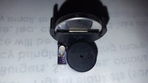
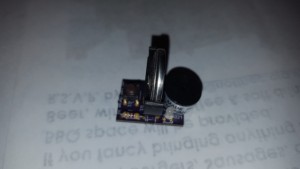
20160427_172802 20160427_172810 20160427_172820 20160427_172754

The boards can be ordered from OSH Park and cost £2.20 for 3
Order from OSH Park

MT MT2

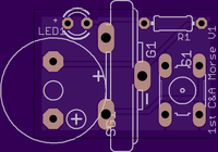
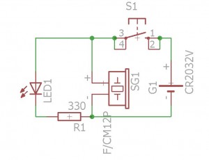
Circuit

morse

BOM

1 x 3mm Led
1 x 1K(or 300R)
1 x Sounder (10 mm pitch) max diameter of 12mm
1 x CR2032 vertical battery holder
1 x CR2032/LR2032 battery
1 x Push button 5mm pitch x 7.5mm pitch

Some Electronic expertise needed, and of course a good soldering teacher.

This project uses Lithium Button batteries, please note the warnings here – Do Not short out the batteries, and Do Not swallow them.

Morse Code
315px-International_Morse_Code.svg

Morse Code decoding “tree”

Morse-code-tree

ALSO

If you wire two boards together (wire the two sounders together with a long bell-wire cable, be careful to get them both the same way around) you can make a telegraph system with a button and sounder at each end. Then you can practice sending and receiving for real….

CONSTRUCTION

Construction details are here


Lichtenburg figure test

Test of transformer choice and wood type for reliable Lichtenberg figures.

Obit – 20Kv 20mA

Both pieces of wood lightly soaked in water (only) just before test.

wood – 4mm MDF

20160420_190448 20160420_190445

Wood length 18″ – each pattern ~6″ across.


Course grained 3 ply

20160420_192526 20160420_192530

Burns only continued in line with the grain. Test abandoned.


New Tesla Coil Phenomenon

After measuring the weight of my new PiZero Tesla coil project setup, I forgot that one of the tesla coils was still on the scales and applied power. I was very surprised to find that the weight of the running coil varied as the power was applied.

I of course instantly thought there was some electromagnetic effect, so I swapped the expensive scales for a cheap plastic (and staggeringly inaccurate) set. These have no metal parts inside apart from a single spring, so cannot be affected by electromagnetic fields. But they clearly showed the same effect (within an order of magnitude) as the other scale. The table the tesla coil was on was wooden and there was no other electrical equipment near by that could influence the scales.

I made a quick video showing the anti-gravity? effect. Please note that the cheap scales have a huge turn back error, and don’t always return to the correct weight, in fact I think they are pretty much useless even for cooking, never mind a scientific experiment.

After making the video I had more time and so did a much better analysis of the effect.

I checked that the wires were not contributing to the effect, if anything they were producing an additional weight due to their natural springiness, but they didnt move either on their own when put near a powerful magnet. I also checked for any static magnetic fields with an orienteering compass and found nothing over and above the earths natural magnetic field.

Futher testing

After further testing it appears that for every 1.5w RMS of energy put into the tesla coil the tesla coil becomes lighter by roughly 1g. Sometimes the effect isn’t immediate (as the video shows) and can take a second or two to appear or disappear. This hints at the building up of a field? around the device.

tcwl

Another possible source of the weight change could have been the ion drive (ion wind) effect, well known to any high voltage enthusiast. I have discounted this for two reasons. 1. The effect looses weight in my setup. 2. The scale of the weight change is far in excess of the force of the ion wind from similar powered tesla coils.

I have tried experiments with a simple low power Royer and Slayer circuits and I have not seen the effect. I suspect that the effect only appears at higher powers. (100W+ ?)


Help with research

I would like for  this observation to be verified by other tesla coilers. If possible please set up a test with you own coil. Please give an idea of the type of coil, the power in, the initial weight of the coil, any weight change (+ or-ve), details of the weighing system used and any notes regarding the effect. I will list the results and coilers details on this page as a central reference for other experimenters. Please note the safety warning below when making measurements.


Further study.

Effect with CW and valve coils.
Effect with static gap and rotary coils. (magnifiers?)
Accurate weighing of running high power Fly-back circuits and car ignition coils.
Industrial Inductive heating – reported effects of the molten metal suspended in the working coil, a connected phenomenon ?


Other Thoughts.

Did Tesla know of this effect ?
Probably not, His coils although powerful were very heavy and securely bolted to the floor, it is unlikely he would have noticed the small change in the weight of his devices.

Electric space propulsion – microwave thrusters or quantum vacuum plasma thrusters (QVPT)
http://ntrs.nasa.gov/search.jsp?R=20140006052
There is a lot of similarity with these devices, they  both use high voltage and work with large RF fields, maybe there is a connection?


Warning / Safety

As modern tesla coils become smaller, lighter and more powerful, the above effect could have more and more significant effects on these tesla coils.  I would strongly suggest that when running any tesla coil they are securely fastened to the ground with a safety chain and the possibility of loose/floating tesla coils should be included in any risk assessment until we know more about this phenomena.

Any questions regarding this effect, or to give your own results for inclusion on this page, please contact tesla@extremeelectronics.co.uk


UPDATE 1/4/16

As of midday today all of the observed behaviour has stopped and I cannot repeat the findings. I can only assume this was a glitch in the space time continuum that lasted for 12 hours.


RPI I2C interface to Microchip embedded uP – Clock stretching

If you are going to implement I2C to an embedded uP read this first http://www.slate.com/blogs/bad_astronomy/2016/03/28/psychedelic_stroboscopic_easter_eggs.html

If you are using a Microchip uP you might want to continue reading.

Here is the problem, Raspberry Pi’s I2C software can’t cope with slave clock stretching, not a problem if you can service the data request quickly, well you would have thought not anyway. Unfortunately Microchip’s hardware (using a PIC18F14K50 and many others)  always puts in a small clock stretch for a slave transmit, even if you disable clock stretching with the SEN bit.   A thorough read of the data sheet gives you a clue “The ACK pulse will be sent on the ninth bit and pin SCK/SCL is held low regardless of SEN“.

So data transmission TO the PIC works fine (if you can deal with the I2C data quickly enough), but for Slave data transmit TO the RPI you get errors. The problem is, they are random and depend on the exact timing of the I2C bus and uP speed.

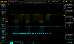
This clock stretch only happens after the address byte and before the transmission data. It causes a short or missing clock pulse (as the RPI ignores the presence of the clock held low by the slave) as in the transition of bytes 3 &4  of data in the oscilloscope capture below.

DS1Z_QuickPrint7

So how do we work around this, well to be honest there isn’t a total solution. (that I’ve found) the best that I have achieved is to change the I2C clock speed  so the timing of a clock stretch happens when the clock is already low and tweak the uP interrupt software.

The clock speed change is unfortunately a trial and error process whilst monitoring the data (and probably watching with a scope). To change the I2C bus speed with a newer PI distro, you need to edit the /boot/config.txt and edit or add the line “dtparam=i2c1_baudrate=clockspeed” try clock speeds from 20000 to 400000 and follow by a reboot of the PI to make the changes active.

The bus clock speed that will work will vary with the microprocessor speed,  so there is no single solution. With my setup 200Khz and 50Khz works well (uP clock @32Mhz) where 400khz and 100khz is a total wright off.

I have also changed the I2C code in the PIC18F14K50 to give a fast set of the  BF flag after data transmission which helps minimise the clock hold time.

if (PIR1bits.SSPIF) {
      
        if (!SSPSTATbits.D_NOT_A) {
            //
            // Slave Address
            //
            i2c_byte_count = 0;

            if (SSPSTATbits.BF) {
                // Discard slave address
                sspBuf = SSPBUF;    // Clear BF
                SSPSTATbits.BF=1;
            }

            if (SSPSTATbits.R_NOT_W) {
                // Reading - read from register map
                SSPCON1bits.WCOL = 0;
                SSPBUF           = i2c_reg_map[i2c_reg_addr++];
              
            }

        } else {
            //
            // Data bytes
            //
            i2c_byte_count++;

            if (SSPSTATbits.BF) {
                sspBuf = SSPBUF;    // Clear BF
                
            }

            if (SSPSTATbits.R_NOT_W) {
                // Multi-byte read - advance to next address
                SSPCON1bits.WCOL = 0;
                SSPBUF           = i2c_reg_map[i2c_reg_addr++];
                SSPSTATbits.BF=1;
               
            } else {

                if (i2c_byte_count == 1) {
                    // First write byte is register address
                    i2c_reg_addr = sspBuf;
                } else {
                    // Write to register address - auto advance
                    //   to allow multiple bytes to be written
                    i2c_reg_map[i2c_reg_addr++] = sspBuf;
                }
            }
           
        }//else
        
        SSPCON1bits.CKP = 1;            // Release clock
        // Limit address to size of register map
        i2c_reg_addr %= sizeof(i2c_reg_map);

        // Finally
        PIR1bits.SSPIF  = 0;            // Clear MSSP interrupt flag
      
    }   
With these changes, I have got (as the adverts say) up to 100% TX from a slave without error. This is about the best we can do until either Microchip change their hardware, or RPI write a I2C handler that supports clock stretch.


Nottingham Gaussfest 2016

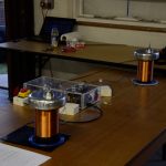
My Coils, static machines and Twin PiZero TeslaCoils

An amazing day, all my coils and static machines worked from beginning to end with no issues. The VDG performed well after a hail storm had knocked out all of the moisture from the air. It made a huge difference. I did however have a failure the night before the Gaussfest (therefore it cant count as a failure AT the Gaussfest) where I shared the earth from my VDG with the PiZero coils. A strong discharge killed the i2c on my Pi Zero. A swap of PiZeros, a number of downloads and a recompile got me back working in a hour or so. Glad I’d gone with the PIZero saved me £21 over a full Pi Failure.


Roger’s VDG

Roger was new to the Gaussfest and brought his commercial VDG, a very nice unit with LOADS of accessories. It ran fairly well during the day after he replaced the original 15year old+ belt. I suspect he suffered with the damp as well, but it didn’t affect his VDG as much as mine, I put this down to a lack leakage from his very smooth top terminal. (The VDG’s not his).


Steve’s coils


Steve brought a couple of coils and a VDG (sorry no photo) . His desktop Static gap coil was a good solid performer, but his VTTC was just a work of art. It performed well with those lovely straight arcs characteristic of VTTC’s. He vows to return to Cambridge, can’t wait.


Jason’s Coil

Jason’s coil ran very well, until he had a capacitor failure, which was a great shame, but hopefully easy to rectify.

Daves coil

Dave’s coil ran well as usual. Superb looking and a very reliable performer. I know Dave has plans for an upgrade, so look forward to the MkII


Phil & Phil’s coils


Slow motion (90fps capture)

Phil and Phils coils (now share so many parts I can’t tell them apart, I’m not sure their owners can either). Both coils ran very well giving 8-10′ arcs to the floor,ceiling and occasionally to a target earth. PhilS did have a problem with a stray topload cable that caused a secondary strike

DSC_1425

It didn’t appear to have done much damage, but only a strip down will tell.


Thanks to everyone that came and especially those who brought “stuff” to demonstrate. After talking to a couple of non-UK visitors they are very envious of our Teslathons, there are very few across the world, and the UK has two!

DSC_1323

See you all at the next Gaussfest or at Cambridge.


Other Photos / links from the event.

Steve Lane

https://plus.google.com/u/0/photos/+SteveLane/albums/6258914846725227377


Strontium breakouts

A test of breakout points made almost entirely of Strontium. The idea is that rather than containing the Strontium in a tube that needs to withstand the heat of an arc, we make a breakout with as much Strontium as possible. Of course Strontium is quite a good insulator so we need to add in a conductive component and something to hold it all together. This test uses PVC glue as the binder and bear conductive ink as the conductor.

tmp_24485-20160117_1901352034523555tmp_24485-20160117_1857471367784658tmp_24485-20160117_185517775580088tmp_24485-20160117_185414-1425974767

Initial tests on a large rotary classic tesla coil

DSC_1015DSC_1013DSC_1005DSC_1263_NEF_embedded


Some effect, but not as strong as Id hoped. Although the one on the chicken stick wasn’t bad.

SSTC 1Kw Much better results.


DSC_1097 DSC_1109 DSC_1111 DSC_1116

A great improvement on any other methods that I have used, and better still, the breakouts seem to be quite resilient and can be used multiple times.

Time to try other mixes 🙂