Category Archives: Blog

Vigo Tec VG-A4 Writer/Engraver

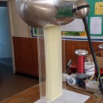
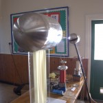
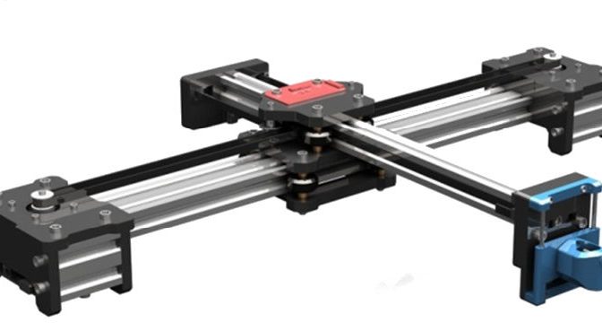
I wanted to a cheap XY plotter to try some experiments and after looking at ebay I saw an inexpensive plotter to try, the Vigotec VG-A4

Construction was fairly easy, although the only instructions that came with the package were in Chinese. I have since found the instructions here Although due to translation issues, they are not much more help.

The Plotter was constructed and worked first time as a writer using the example JPG’s and the VigoTec Writer Software. (Downloadable here )

Be careful about belt tightness. If the belt it too tight you will easily loose position when moving. Otherwise the hardware is well made an designed.

I haven’t yet tried the Engraver software as this involved changing the firmware in the driver board.

All working well, I started to try driving the plotter by G-Code. There is of course Zero Documentation.

So after a lot of trying things I found the PenUP/Pen Down commands which are M03 and M05 respectively. You will need a delay for the pen server to do its thing, Im currently using G4 P1000 to give a 1 second delay.

This mostly works, as a test I put in a move G1 X Y Z and a pen down followed by a pen up. I did this 4 times to create a dot in each corner of a square, The pen only responded to two of them, I have no idea why.

The Writing software is very buggy. With many of the adjustments not working at all. I also find that you MUST do a pen down then a pen reset before using G-Code otherwise the pen wont work at all. (The pen UP button appears to do nothing. Unless you have loaded an image).

Be careful using G0 the plotter appears to lose position even with the lightest of pens. To cure this and especially if you are using anything heavier, use a G1 X Y Z FXXXX to set the feed rate. ( When using G-Code the speed slider is ignored)

There are some issues with G1 and pen up/down, but I haven’t fully discovered what the causes to these are or any solutions yet.

Flashing light prize 2017

Details for the entry for the 2017 flashing light prize.

The Flashing Light Prize  is an informal & fun contest to find the most unusual way of flashing an incandescent light bulb.

So, being me, it had to include high voltage, and It had to use what I had lying around as I’ve been quite short of time recently.

My Wimshurst came to mind, but I wasn’t sure the two laden jars would hold enough energy to light a lamp. A quick test proved that as long as I was using small lamps, there was plenty of power available.

My initial tests failed, as the leads from the bulb made a point source that leaked charge away from the Wimshurst, so it never charged up to enough voltage. This was an easy fix, I attached a 1/2″ brass ball onto the bulb leads, with a 12mm Gap I go a flash rate of ~1Hz and ~40,000V, plenty for a 6v bulb 🙂

I had a few 6V 30ma Grain of wheat bulbs and these flashed really well from the sparks from the Wimshurst. The problem was after about 4 flashes that only just lit the bulb the filament would explode and leave a small arc lamp behind.

My thought was that the thermal shock from having 40,000V dumped into the filaments (rather than 6v) was probably something to do with the failure. I started to look around for a large HV inductance that would limit the inrush.

An Ignition coil secondary was put in series with the bulb and then I had a second thought, use it as a transformer to power the bulb at lower voltages.

So two bulbs were connected across the Ignition coil primary and the secondary was put via a spark gap across the Wimshurst terminals.  This flashed really reliably.  Power and speed could be varied with the spark gap, although at full separation the bulbs looked excessively bright so the rate was kept quite small.
2017 flashing light entry video


Wimshurst machine details/build


Incredibly, I won with this entry … So Chuffed !

Can’t wait until September to defend the title …

https://www.flashinglightprize.com/ 

Flashing light challenge 2017 my second entry

Lichtenburg figures for the BBC One Show

Ok so it started as one of those phone calls that asks if I can make safe sparks. Quite a regular ask for me and I always start with no. High voltage isn’t safe.

Anyway after a number of discussions. I was asked to make a “relatively” safe way of allowing a BBC presenter to create lichtenburg figures.

The method I came up with was to use a 15KV OBIT (Oil Burner Ignition Transformer). I prefer this type of transformer to a MOT (Microwave Oven Transformer) for purely safety reasons. One touch from an MOT and you are either Burnt, Dead or Burnt and Dead, Not good odds. This is due to them giving up to 100mA at 2KV, plenty to get 1-2mA across the heart of the unwary. The other issue with MOT’s is they are low enough voltage not to cause corona, which means they are silent, a dangerous mix. OBITS on the other hand give out 10-15Kv at 5-10mA. Not safe, but you are much more likely to survive an accidental contact.  Also due to the OBITs high voltage, you can hear when they are on.

The Control.

20160704_152207

20160704_152117

The boxes were split in to two, the Transformer and high voltage at the “HOT” end and the lower voltage (mains) at the other.

The control box had a key lockout which needed to be in place for the HV to be turned on. This key was attached to me with a short lead so I could ensure the HV area was safe before I allowed any power to the box. The Go button was momentary, so that if any danger was spotted the power could be quickly removed.

The HV end was in a roped off area (out of shot)

The mains was supplied via an earth leakage trip for added safety.

20160426_123838

The HV end was supplied via 30KV insulated cable to two crock clips that attached to the screws on the board.

The board was dampened with water and washing up liquid, (required to properly soak more than just the surface of the board)

20160426_131831

This really is a don’t try it at home experiment, when the power is on, you can’t touch ANYTHING, damp wood, water and high voltage  not a good mix.

Luckily the presenter was Marty Jopson a HV fan so the explanation and safety briefing was fairly easy as he understood the risks. (He has his own collection of HV equipment including a one Tesla.)

20160426_125954sm

This was all done in the most glamorous of locations 🙂

20160426_123534

The result. No one died… and I think they got a good film of the Lichtenburg figures being produced.  I will find out 19:00 BBC1 4th July 2016.

Other Making Lichtenburg links

Lichtenburg figures with toner

Lichtenburg figures over water

Lichtenburg figures in wood.


Save

Save

Save

Save

Save

Save

Save

Save

Headless Raspberry PI (PIZero) setup

The PIZero Simple setup without network or monitor. (Requires some prior knowledge of RS232 adapters and serial port setup)

First start by getting a PI SD image I used Raspian Jesse Light https://www.raspberrypi.org/downloads/raspbian/

Install into a sd card and make sure it runs (green light at least)

With a 3.3v RS232 adapter connect earth and RX/TX to your PI. Be careful some adapters are only 5V and will damage your PI’s UART pins.

PiZero

Setup your PC (I use Tera Term) serial adapter for 115200, 7 bits, even parity, 1 stop bit.

Boot your PI

If you get a screen of gobbledegook then good, otherwise swap your TX and RX around. When the gobbledegook has finished, press return a couple of times, and you should get a login prompt.

For some reason the console and boot up output at different baud rates (Caused by auto baud rate detect, settings above amended so this shouldn’t happen now)

Configure your PI the usual way. You will need some network to get your updates, but apart from that you have a working PI.

If you are brave (or idle) you can connect the +5v line from your serial adapter to power your PI too so you don’t need another usb power lead. Just be very careful that you attach it to the correct pins, otherwise your PI will be damaged.


Useful links.

(although I found the baud rate setting wrong everywhere I looked. Either auto baud rate detect at work, or it changes from distro to distro)

Element 14 no display using the raspberry pi serial console

RPi Serial Connection


Update:

The baud rate is auto detected, the native speed is 115200 (amended above) The auto detection only happens at the login prompt. The auto detection won’t pick up changes in bits/stop bits/ or parity. You can change the console getty port/speed/parity settings look at RPi serial connection above.

WiFi

If you have a wifi adapter and micro USB to USB lead, you can connect to WIFI. After connecting via RS232 edit the file /etc/wpa_supplicant/wpa_supplicant.conf using sudo nano

add in the lines

network={
    ssid="Your_WIFI_SSID"
    psk="Your_wifi_password"
}

and reboot the pi sudo shutdown -r

re log in to the pi and type ifconfig to fins the wifi IP address. 
Then you can ssh to your PI and even better update the software.

Note : for Pi 3. You may need some changes to get the headless conf working, especially at non default baudrates, take a look at http://www.briandorey.com/post/Raspberry-Pi-3-UART-Boot-Overlay-Part-Two


Static electricity doesn’t exist

Yes, I know, its was taught to you at school. Me too.  I even have a book that has separate chapters of static electricity and conventional current electricity. So what is the problem, well it took me years to work out that there is no such distinction. Its all electricity. Static electricity on the terminal of a VDG sphere doesn’t suddenly transform in to current electricity when it is discharged and current electricity doesn’t transform into static when its stored in a capacitor.. The same rules must apply to both.

To use the water analogy, water is the same if its in a lake or  in a stream.

I’m my mind I can’t think of any situation where static electricity exists. Capacitors, Van de graph terminals (also capacitors) all store charge. But non are static, there is always leakage current. To charge these devices there must be current.

So is its not static electricity, its stored electricity (charge) or conventional electricity(current) ,  both or just electricity.

Reading Physics books there appears to be a whole set of laws that govern each “type” of electricity, but in reality the effects are always there. One of the problems is that ‘static’ electricity is generally taught with high DC voltages, current electricity is taught with low DC voltages. The effects you see are dominated by the voltage, for example.

Electrical attraction occurs in all capacitors. But at high voltage the effects are much larger and so easier to see.
Resistive heating has a larger effect at low voltages, but is harder to see at high voltages (which is why transmission lines are high voltages)

The more you work on high voltage, or with high frequency electricity the more these effects become apparent.

So banish ‘static’ as a description and replace with high or low voltage, charge or current this is really what is going on.

Bill Beaty’s Thoughts on this What’s the Difference Between ‘Static’ Electricity and ‘Current’ Electricity?

1MV Van De Graff project – Notts Gaussfest

After a lot of work, I just managed to get everything to Notts Gaussfest. This was really the first time all of the pieces had run together for any length of time.

I found a number of issues. The belt stuck together at high charges, usually stopping the belt completely and the motor control would crash when there was a really good discharge.

The motor problem was a partially solved by coating the controller in aluminium foil, which at least let me run the VDG for the day at Notts Gaussfest.


1MV Van de Graff – First light

Details of the project

First light tonight 6″ sparks, not bad for the first time I’ve powered it up.

At the moment the limiting factors to the spark length/voltage is the unfinished top load and a problem with the belt. The top load has a very uneven surface, I believe I’m losing charge this way.

When the VDG starts charging the two sides of the belt are attracted to each other and they rub together, reducing the charging. I tried tightening the belt with no effect, so I have ordered 0.4mm (was 0.25mm) latex to make another thicker belt.

Work continues to complete the top load.